August 1999 76-100016-001
PEGAsys
Intelligent Suppression Control/Fire Alarm System
3-6
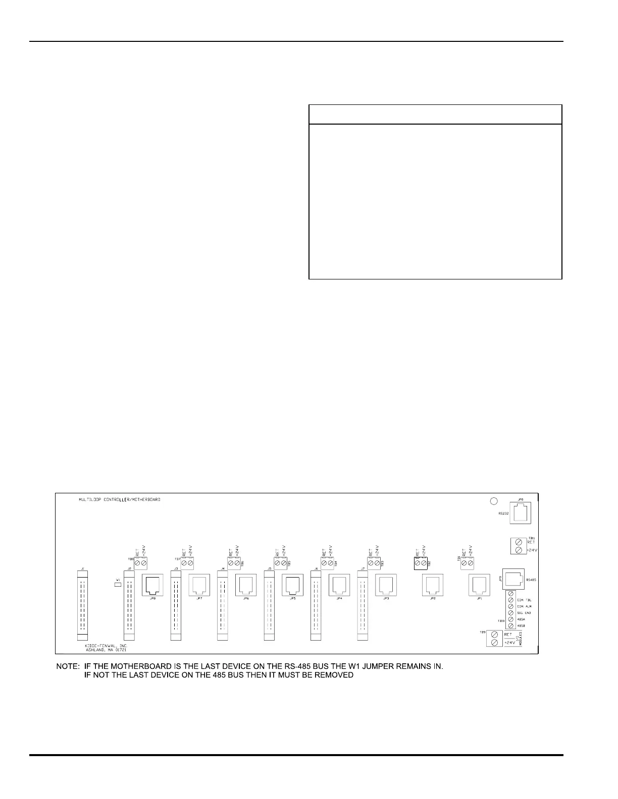
Figure 3-7. Multi-Loop I/O Motherboard, Details
3-3.5 Multi-Loop I/O Motherboard
The multi-loop I/O motherboard assembly, P/N 76-100017-001,
is an assembly which can accept any combination of 9 mod-
ules consisting of up to 8 RX/TX modules and provide connec-
tions for up to 7 I/O module circuit board assemblies. The ML
motherboard is mounted to standoffs on the back of the main
system enclosure. It distributes the system 24 VDC power, CCM-
RX/TX communications modules and I/O bus communications
to the I/O modules. The I/O bus communications are provided
by a RJ-12 (flat phone cable) style connection. A single RJ-12
connection connects the ML motherboard to the CCM for RX/
TX communications. The 24 VDC is provided by the system
power supply via a 2 conductor wiring harness connected to a
terminal block (TB9) is distributed through terminal blocks (TB1-
TB8) for connection on RX/TXs. The 24 VDC provided by the
system power supply via 2 conductor wiring connected to ter-
minal block TB-11 is distributed through I/O bus slots for power-
ing I/O modules.
The RX/TX module communicates to the CCM via the multiplexer
located on the motherboard. The CCM identifies each of the in-
stalled RX/TX modules by the RS-232 connection on the
motherboard. The table below lists each RX/TX communication
connection located on the motherboard and the loop number and
addresses assigned to the connected module. Refer to Drawing.
No. 06-235443-012, in Appendix I, for installation details.
Table 3-1. Multi-Loop I/O Motherboard Connectors
ROTCENNOCPOOLSSERDDA
1PJ1 5521-1001
2PJ2 5522-1002
3PJ3 5523-1003
4PJ4 5524-1004
5PJ5 5525-1005
6PJ6 5526-1006
7PJ7 5527-1007
8PJ8 5528-1008