August 1999 76-100016-001
PEGAsys
Intelligent Suppression Control/Fire Alarm System
3-8
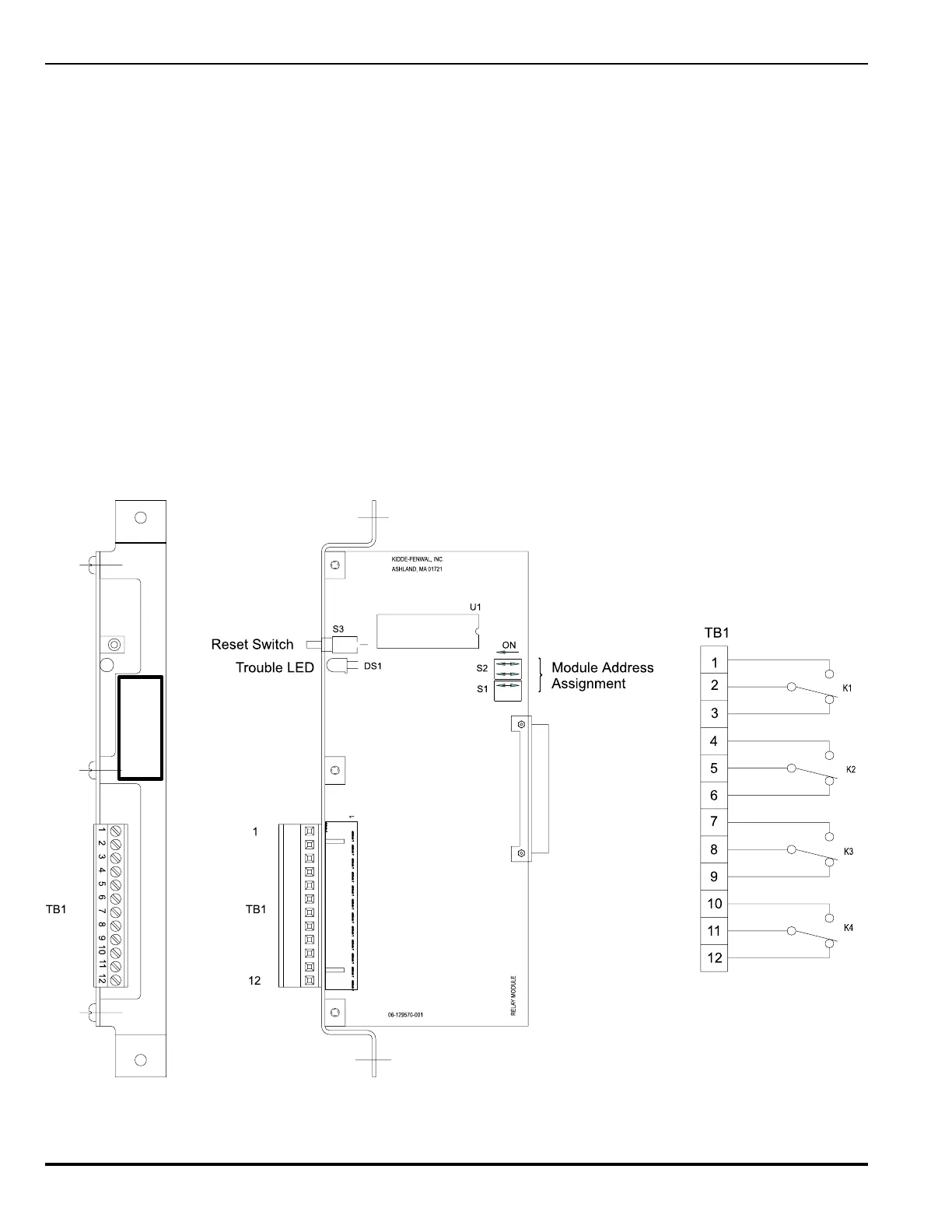
Figure 3-9. Relay Output Module, Details
Note: A maximum of 8 Relay Output Modules can be used on the system. Refer to paragraph 1-2.7, in Chapter 1, for other limitations.
RELAY
76-100004-001
3-3.7 Relay Output Module
The PEGAsys panel has the capacity for a maximum of 8 Aux-
iliary Relay Output cards for up to 32 relays. Each Auxiliary
Relay Output card (shown in Figure 3-9) is equipped with 4
Form C, dry contact relay outputs. The ability to isolate an indi-
vidual relay output is accomplished through the system opera-
tor menu.
The auxiliary relays are rated for 2.0 Amp @ 30 VDC & 1.0 Amp
@ 120 VAC. Refer to Drawing. No. 06-235371-007, in Appen-
dix I, for further installation details.
Each relay output can be individually programmed via the PCS
program for operation. Relation between each relay output and
its input source is defined by the panel EOC logic program. In
Walk Test mode the relay output circuit(s) will not operate when
the input device(s) under test are activated.