August 199976-100016-001
Intelligent Suppression Control/Fire Alarm System
PEGAsys
7-7
Figure 7-10. Battery Enclosure
7-10 FIELD DEVICE CONNECTION TO RX/TX
MODULE
Field devices connect to terminal block (TB1) located on the
PEGAsys System’s Receiver/Transmitter (RX/TX). The cable
connecting the field devices to the RX/TX module provides power
and bidirectional communications to the loop devices. One RX/
TX module can support up to 255 SmartOne addressable field
devices. These 255 addresses can be any mixture of intelligent
loop device inputs and outputs without restriction to amounts of
either inputs or outputs.
NOTE: All Non Power Limited wiring must be routed away from
Power Limited wiring by a minimum of 1/4", per NFPA
& UL requirements. For Power Limited Circuits use
Type FPL, FPLP, or FPLR cable per NEC Article 760.
7-10.1 Wiring the RX/TX PC Line
The RX/TX PC line uses Broadcast Indexing Protocol (BIP) for
communications with intelligent loop devices. The PC Line may
be configured in NFPA-72, Style 4, 6, or 7. The PC Line is ca-
pable of supporting 255 intelligent loop devices on a 2-wire loop.
In retrofit applications, existing wiring can be used as long as it
meets NEC 760 and NFPA 72 requirements. When installing
new wiring or using existing wiring it is necessary to check line
resistance and capacitance. Total line resistance can not be
greater than 26 Ohms, and capacitance can not exceed 1.0
microFarad. Kidde recommends that you use No. 18 AWG mini-
mum wiring as the connection cable between the RX/TX Mod-
ule and the field devices
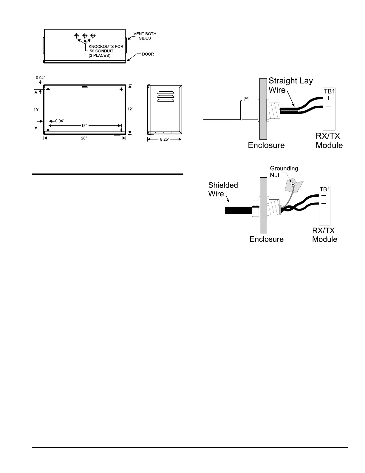
The PC line to the loop devices can be run in conduit to the
Central Control Panel cabinet. The conduit, if used must be
attached through any convenient Central Control Panel enclo-
sure knockout. Route the connection cable to TB1 on the RX/
TX PCB, and insert the end of each connection cable wire into
its proper TB1 slot and tighten the slot screws firmly. See Fig-
ure 7-11.
In retrofit applications where the PC line of the RX/TX may be
mixed in an existing conduit with appropriately loaded output
circuits (signal & release), using unshielded cable for all cir-
cuits is only recommended when all output devices connected
are Kidde products. All conduit and conductors must meet NEC,
NFPA-72 and any applicable local code requirements. See Fig-
ure 7-12 for shielded cable termination. Optionally, the PC line
can be installed in a separate conduit as shown previously, thus
allowing the PC line to remain straight lay wire.
Figure 7-11. Conduit to CCP
Figure 7-12. Shielded Wire to CCP
NOTE: All new RCUs are shipped from Kidde with their address
set to 000. This address is reserved for unregistered
devices and cannot be used as a registered address.
You must connect unaddressed devices to the RX/TX
Module one at a time in order to address them.
Otherwise you may pre address devices using the hand
held device programmer (P/N 74-200013-001) and
connect multiple pre-addressed loop devices to the RX/
TX PC line at the same time.
Table 7-1 lists the types of allowable configurations you can
select along with the respective jumper settings for those con-
figurations. As described in this chapter the PC line can be con-
figured in Style 4, 6, or 7. Each Style is represented in Figures
7-13 through 7-16.
Style 4 configurations allow T-tapping. T-tapping is only limited
by sound installation techniques.