August 199976-100016-001
Intelligent Suppression Control/Fire Alarm System
PEGAsys
7-5
attribute?
attribute?
attribute?
attribute?
attribute?
attribute?
attribute?
24V
RET
AC OUT
1
AC IN
2
24V
RET
NLNL N
DC IN 1
LG
DC IN 2
SPV
SPV
SHARE
WHT
BLK/WHT
BLK
BLK
VIO
RED
RED
ORN
WHT
BLK/WHT
ORN
RED
BLK
VIO
BLK
RED
MAIN POWER SUPPLY
(76-100009-010)
AUXILIARY POWER SUPPLY
(76-100009-002)
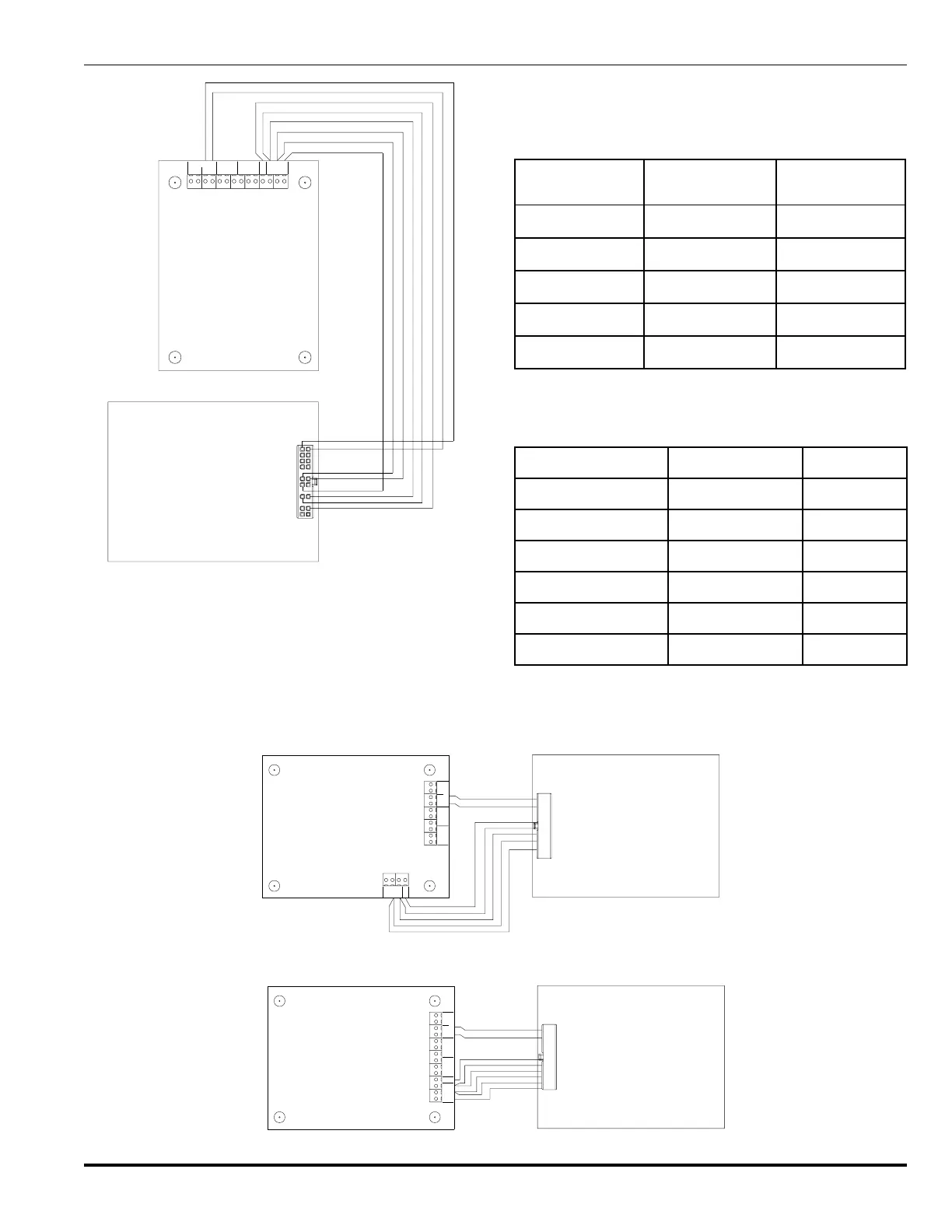
Figure 7-7. Power Supply/Charger (Rev C), Wiring Diagram
e. Set jumpers in accordance with drawing 06-235443-003
(located in the back of this manual).
f. Install module in the desired position on the back plate of
the expansion enclosure.
g. Insert and tighten the four mounting screws into the four
corners of the mounting plate.
Table 7-2. Aux. Power Supply Module Connections to Rev A,
Main Power Supply/Charger Assembly
rewoP.xuA
ylppuS
noitcnuFylppuSniaM
etihW)lartueN(tupniCA)N(31BT
etihW/kcalB)toH(tupnICA)L(31BT
deR).soP(tuptuOCD)CDV42(9BT
kcalB).geN(tuptuOCD)teR(8BT
egnarOerahS)RHS(9BT
Table 7-3. Aux. Power Supply Module Connections to Rev C,
Main Power Supply/Charger Assembly
ylppuSrewoP.xuAnoitcnuFylppuSniaM
etihW)lartueN(tupniCA)N(31BT
etihW/kcalB)toH(tupnICA)L(31BT
deR).soP(tuptuOCD)CDV42(9BT
kcalB).geN(tuptuOCD)teR(8BT
teloiVnoisivrepuS)VPS(8BT
egnarOerahS)RHS(9BT
Figure 7-8. Power Supply/Charger (Rev A), Wiring Diagram for Expansion Enclosure
Figure 7-9. Power Supply/Charger (Rev C), Wiring Diagram for Expansion Enclosure
WHT
BLK/WHT
BLK
BLK
RED
RED
ORN
attribute?
attribute?
attribute?
attribute?
attribute?
AC OUT
1
AC IN
2
24V
RET
N
L
N
L
N
DC IN 1
L
G
SPV
attribute?
attribute?
24V
RET
DC IN 2
SHARE
MAIN POWER SUPPLY
(76-100009-001)
AUXILIARY POWER SUPPLY
(76-100009-003)
RET
WHT
BLK/WHT
BLK
BLK
VIO
RED
RED
ORN
attribute?
attribute?
attribute?
attribute?
attribute?
attribute?
attribute?
24V
RET
AC OUT
1
AC IN
2
24V
RET
N
L
N
L
N
DC IN 1
L
G
DC IN 2
SPV
SPV
SHARE
MAIN POWER SUPPLY
(76-100009-010)
AUXILIARY POWER SUPPLY
(76-100009-003)