August 1999 76-100016-001
PEGAsys
Intelligent Suppression Control/Fire Alarm System
7-2
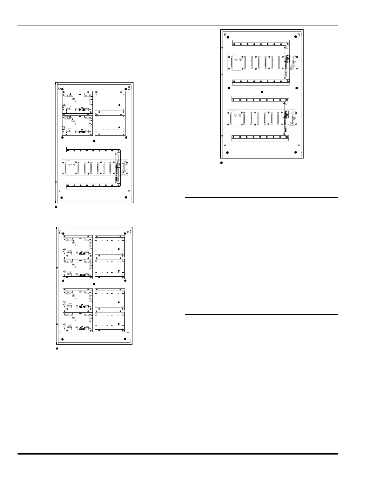
ure 7-3 shows the expansion backplate which provides mount-
ing for up to 8 auxiliary power supplies. Figure 7-4, shows the
expansion backplate which provides mounting for two I/O moth-
erboards.
To install, position the back plate in the enclosure and fasten it
to the seven studs located in the enclosure using the nuts sup-
plied with the enclosure.
= Back Plate Mounting Studs (7 Locations)
0
6
-1
2
9
5
6
2
-0
0
1
N
O
N
C
RS485
A
B
CCM
MOTHERBD
SYSTEMPOWER
24V
RET
24V
RET
2
4
V
R
E
T
2
4
V
2
4
V
R
E
T
R
E
T
2
4
V
R
E
T
BAT
+
-
A
U
X
1
A
U
X
2
DCIN 2
C
D
C
IN
1
A
C
O
U
T
N
1
L
2
N
G
L
N
A
C
IN
24V
L
SHR
RET
S
H
R
TP4TP3
D
S
1
S
3
TB9TB8
R
R
2
1
1
2
S
1
ASHLAND,MA 01721
KIDDE-FENWAL,INC.
R
E
T
TBLRELAY
TBLRELAY
W2 W3
W
4
F1
W1
S
2
0
6
-1
2
9
5
6
2
-0
0
1
N
O
N
C
RS485
A
B
CCM
MOTHERBD
SYSTEMPOWER
24V
RET
24V
RET
2
4
V
R
E
T
2
4
V
2
4
V
R
E
T
R
E
T
2
4
V
R
E
T
BAT
+
-
A
U
X
1
A
U
X
2
DCIN 2
C
D
C
IN
1
A
C
O
U
T
N
1
L
2
N
G
L
N
A
C
IN
24V
L
SHR
RET
S
H
R
TP4TP3
D
S
1
S
3
TB9TB8
R
R
2
1
1
2
S
1
ASHLAND,MA 01721
KIDDE-FENWAL,INC.
R
E
T
TBLRELAY
TBLRELAY
W2 W3
W
4
F1
W1
S
2
Figure 7-2. Back Plate, I/O Motherboard & 4 P.S.
= Back Plate Mounting Studs (7 Locations)
0
6
-1
2
9
5
6
2
-0
0
1
N
O
N
C
RS485
A
B
CCMMOTHER BD
SYSTEMPOWER
24V
RET
24V
RET
2
4
V
R
E
T
2
4
V
2
4
V
R
E
T
R
E
T
2
4
V
R
E
T
BAT
+
-
A
U
X
1
A
U
X
2
DCIN 2
C
D
C
IN
1
A
C
O
U
T
N
1
L
2
N
G
L
N
A
C
IN
24V
L
SHR
RET
S
H
R
TP4TP3
D
S
1
S
3
TB9TB8
R
R
2
1
1
2
S
1
ASHLAND,MA 01721
KIDDE-FENWAL,INC.
R
E
T
TBLRELAY
TBLRELAY
W2 W3
W
4
F1
W1
S
2
0
6
-1
2
9
5
6
2
-0
0
1
N
O
N
C
RS485
A
B
CCMMOTHER BD
SYSTEMPOWER
24V
RET
24V
RET
2
4
V
R
E
T
2
4
V
2
4
V
R
E
T
R
E
T
2
4
V
R
E
T
BAT
+
-
A
U
X
1
A
U
X
2
DCIN 2
C
D
C
IN
1
A
C
O
U
T
N
1
L
2
N
G
L
N
A
C
IN
24V
L
SHR
RET
S
H
R
TP4TP3
D
S
1
S
3
TB9TB8
R
R
2
1
1
2
S
1
ASHLAND,MA 01721
KIDDE-FENWAL,INC.
R
E
T
TBLRELAY
TBLRELAY
W2 W3
W
4
F1
W1
S
2
Figure 7-3. Back Plate, 8 P.S.
= Back Plate Mounting Studs (7 Locations)
Figure 7-4. Back Plate, 2 I/O Motherboard
7-5 INSTALLATION PROCEDURE FOR I/O
MOTHERBOARD
The following paragraph provides the step-by-step procedure
to install a I/O motherboard into a single loop configured sys-
tem.
a. Place motherboard on standoffs in the back of the enclo-
sure.
b. Insert and tighten the 12 mounting screws provided with
the motherboard.
c. Connect the 24VDC wiring from the power supply to termi-
nal TB1.
d. Connect the RJ-12 phone style wire from the MOTHER BD
connector (on the power supply) to J9 on the motherboard.
7-6 INSTALLATION PROCEDURE FOR RX/TX
MODULE (MULTI-LOOP ONLY)
The following paragraph provides the step-by-step procedure
for replacing the RX/TX module. Refer to Figure 7-5.
Ensure the RX/TX jumpers are set properly during the proce-
dure. Verify that the settings of the jumpers on the RX/TX Mod-
ule conform to the wiring style of the system being installed.
The RX/TX is shipped from the factory programmed for Style 6
wiring style. Refer to Drawing No. 06-235443-002, in Appendix
I, which is the installation drawing which shows the jumper lo-
cations on the RX/TX module. The settings are used to set the
wiring style ( 4, 6 or 7), 7 being used with loop isolators. Jump-
ers on the RX/TX Module are noted by JP x and Wx (x = a
single digit) call-outs on the module board. Table 7-1 lists the
types of allowable configurations you can select along with their
respective jumpers.