August 199976-100016-001
Intelligent Suppression Control/Fire Alarm System
PEGAsys
3-5
POWER LIMITED TO 1.5 A DC
POWER LIMITED TO 1.5 A DC
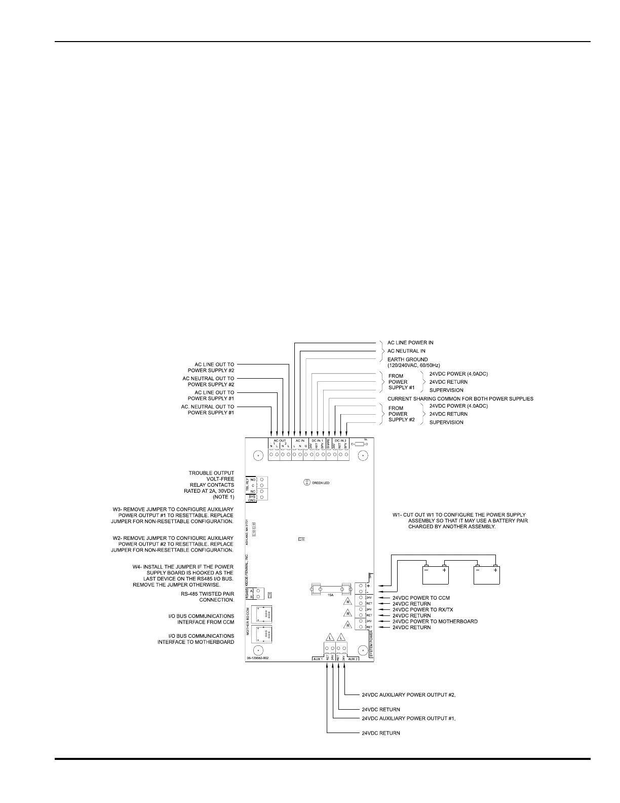
CAUTION: THE VOLTAGE FOR THE TWO BATTERIES IN SERIES MUST
BE GREATER THAN 22 VDC BEFORE CONNECTION TO THE PANEL.
TWO (2) SEALED
LEAD-ACID
BATTERIES
Figure 3-6. Power Supply/Charger Assembly (Revision C), Details
3-3.4 Power Supply/Charger Assembly, Rev. C.
• Battery charging (up to 99 AH) and supervision
• Low Voltage Battery cutoff at 19VDC
• AC power supervision
• 24 VDC supervision
• Battery load test
• 2 auxiliary 24 VDC outputs, programmable for switched or
unswitched configuration
• Trouble relay that transfers upon any power supply trouble
or power off condition (Relay shown in the unpowered state)
The power supply/charger assembly (P/N 76-100009-010) pro-
vides terminal connections for an auxiliary power module. This
module is available with two different wiring harnesses, which
follow:
• P/N 76-100009-002 is supplied with a 36" harness that is
meant to connect a main power supply/charger assembly
to the auxiliary power module in the main cabinet.
• P/N 76-100009-003 is supplied with an 8" harness to mount
a main power supply/charger assembly to an auxiliary power
module in a expansion enclosure.
The addition of an auxiliary power module to the main power
supply/charger assembly will provide an additional 4 amps of
current and make the total available current of 8 amps for this
assembly. The system can support up to 8 main power supply/
charger assemblies with the capability of adding an auxiliary
power module to each one to provide a maximum available cur-
rent of 64 amps. Each additional power supply/charger assem-
bly (P/N 76-100009-010) would need to have a separate address
to operate in the system. The auxiliary power module would
share the same address as the main power supply/charger as-
sembly that it is connected to. Refer to drawing number 06-
235443-003, in Appendix I, for further installation details.
NOTE: The Rev. C. Power Supply/Charger assembly can be
distinguished from the Rev. A. version by the large heat
sink on the right side of the unit.