August 1999 76-100016-001
PEGAsys
Intelligent Suppression Control/Fire Alarm System
7-8
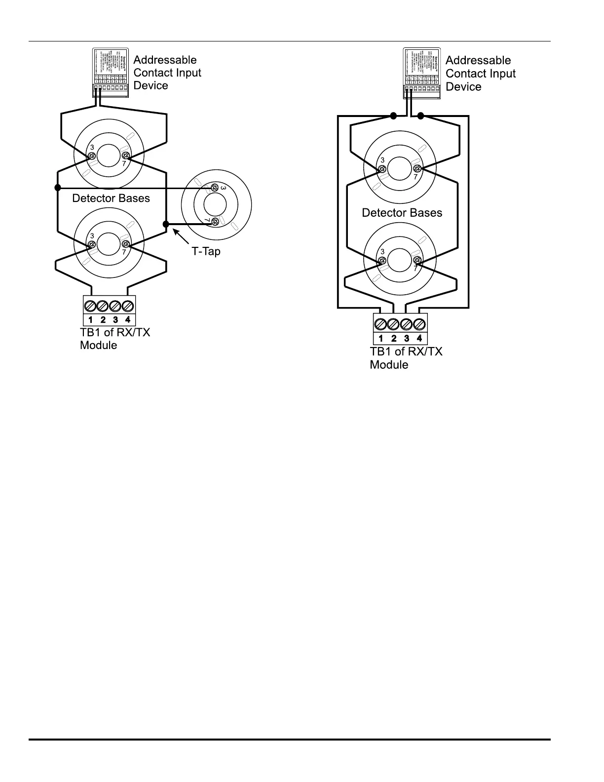
Figure 7-13. Style 4, RX/TX PC Line Connections
In the Style 6 wiring, configuration the RX/TX automatically trans-
mits data and power bidirectionally when a break in the PC line
wiring occurs. If the break is in a single conductor, all loop de-
vices will remain fully operational. For Style 6 PC line connec-
tions, if a PC line open trouble is encountered, use the system
reset switch on the display and control board, or push the bot-
tom button on the RX/TX board, to reset the PC line to normal
once the fault is corrected.
Figure 7-14. Style 6, RX/TX PC Line Connections
Loop Isolator devices are available to support NFPA-72 Wiring
Style 7 and would be installed on the PC line of the RX/TX mod-
ule. Isolator packages are available for electrical box mount
(Single Gang), 6” Base mount and RX/TX mount.
By "flanking" each group of loop devices with a pair of loop
isolators, each zone is protected from opens and shorts. A zone
is defined as a group of loop devices. In this style of installa-
tion, a short circuit between any two loop isolators will not effect
any other zone. The isolators on each side of the short will open
the PC line.