August 1999 76-100016-001
PEGAsys
Intelligent Suppression Control/Fire Alarm System
3-4
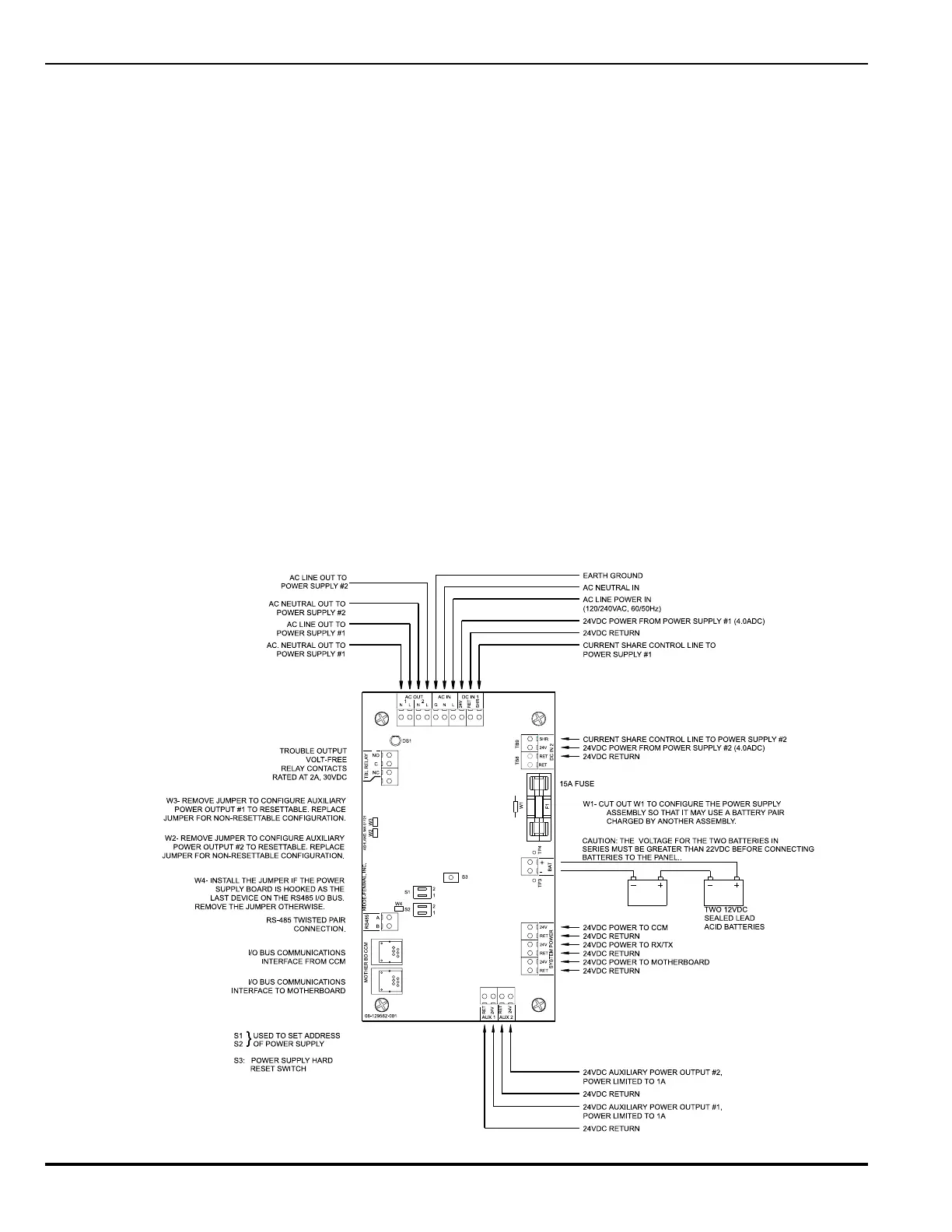
Figure 3-5. Obsolete Power Supply/Charger Assembly (Revision A), Details
3-3.3 Power Supply/Charger Assembly, Rev. A
This power supply assembly was provided with earlier systems.
Information is being provided for service purposes only. The
power supply/charger assembly, Figure 3-5 (P/N 76-100009-
001) is comprised of a printed circuit board (PCB) mounted on
a AC / DC switching power module. The switching power pro-
vides 4 amps of 24 VDC power from the 120 / 240 VAC input
power. The PCB assembly is a microprocessor based unit which
provides the system with
• Battery charging (up to 33 AH) and supervision Low Volt-
age Battery cutoff at 19VDC
• AC power supervision
• 24 VDC supervision
• Battery load test
• 24 VDC ground fault detection (+/-)
• Trouble relay that transfers upon any power supply trouble
or power off condition (Relay shown in the unpowered state)
• Auxiliary 24 VDC outputs (programmable for switched or
unswitched configurations)
The auxiliary 24 VDC outputs rated at 1 Amp each and can be
used to power 4 wire type detection devices such as smoke,
flame and gas detectors which must be sized properly to stay
within output current limits.
The power supply/charger assembly is addressable and com-
municates with the CCM over the I/O bus.
The power supply/charger assembly provides terminal connec-
tions for an auxiliary power module. This module comes with 2
different wiring harnesses, as follows:
• P/N 76-100009-002 is supplied with a 36" harness that is
meant to connect a main power supply/charger assembly
to the auxiliary power module in the main cabinet.
• P/N 76-100009-003 is supplied with an 8" harness to mount
a main power supply/charger assembly to an auxiliary power
module in a expansion enclosure.
The addition of an auxiliary power module to the main power
supply/charger assembly will provide an additional 4 amps of
current and make the total available current of 8 amps for this
assembly. The system can support up to 8 main power supply/
charger assemblies with the capability of adding an auxiliary
power module to each one to provide a maximum available cur-
rent of 64 amps. Each additional power supply/charger assem-
bly (P/N 76-100009-001) would need to have a separate address
to operate in the system. The auxiliary power module would
share the same address as the main power supply/charger as-
sembly that it is connected to. Refer to drawing number 06-
235443-003, in Appendix I, for further installation details.