B-1 August 199976-100016-001
Intelligent Suppression Control/Fire Alarm System
PEGAsys
APPENDIX B
SYSTEM EXPANSION
The PEGAsys system is capable of substantial expansion in the
number of RX/TX loops, I/O modules and system output power.
The system will support up to 16 I/O modules for single loop and
23 I/O modules for multi-loop - a maximum of 8 of any one type of
module. The system power supply monitor module can super-
vise two power supply units (4 amps each for a total of 8 amps
per module) which allows for up to 64 amps of 24 VDC power.
The following diagrams will demonstrate the available ways of
expanding the system.
Figure B-1 shows the single loop PEGAsys system (P/N 76-
100000-501). This includes the Central Control Module (CCM),
Receiver/Transmitter (RX/TX) module, Power Supply/Charger
assembly and the system enclosure. The basic system can be
expanded as shown in the following sections
06-129562-001
NO
NC
R
S
48
5
A
B
C
C
M
M
O
T
H
E
R
B
D
S
Y
S
T
E
M
P
O
W
E
R
2
4
V
R
E
T
24
V
R
E
T
24V
RET
24V
24V
RET
RET
24V
RET
B
A
T
+
-
AUX 1
AUX 2
D
C
IN
2
C
DC IN 1
AC OUT
N
1
L
2
N GL N
AC IN
24
V
L
S
H
R
R
E
T
SHR
T
P
4
T
P
3
DS1
S3
T
B
9
T
B
8
R
R
2
1
1
2
S1
A
S
H
LA
N
D
,
M
A
0
172
1
K
ID
D
E
-F
E
N
W
A
L
,IN
C
.
RET
T
B
L
R
E
L
A
Y
T
B
L
R
E
L
A
Y
W
2
W
3
W4
F
1
W
1
S2
PEGAsysKIDDE
Figure B-1. Single Loop
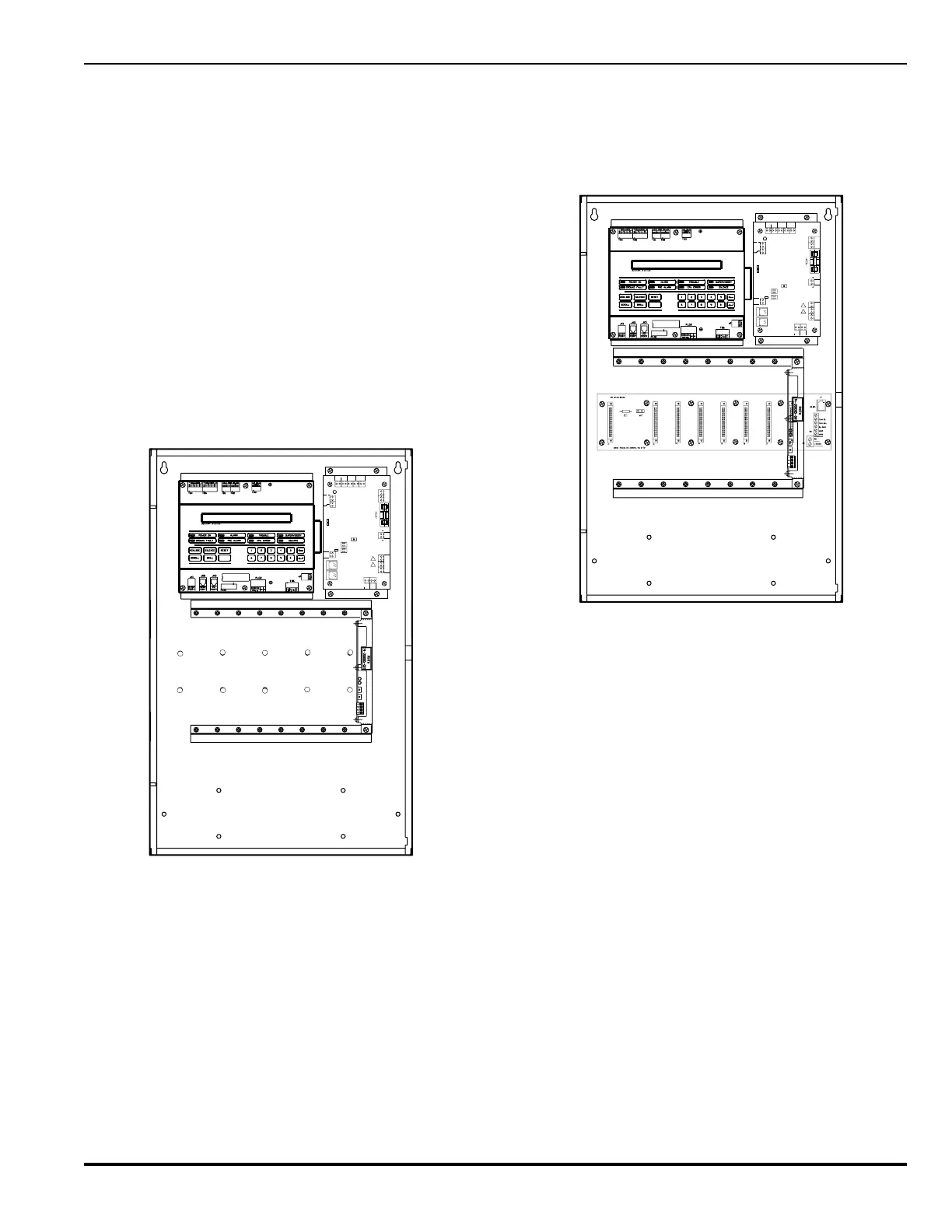
Figure B-2 shows the single-loop PEGAsys system with the
optional I/O motherboard (P/N 76-100007-001) installed. The I/
O motherboard provides the system with mechanical and elec-
trical interfaces for up to eight I/O modules of any style. The I/O
modules are installed by inserting them into the desired
motherboard slot and fastening with the two screws provided.
The PEGAsys ML (Multi-loop) system (P/N 76-100000-600) looks
much the same as the system in Figure B-2 with the exception of
the multi-loop motherboard (P/N 76-100017-001) in the place of
the basic motherboard (P/N 76-100007-001). The Multi-loop
motherboard has the ability to connect up to 8 RX/TX loop con-
trollers, for a maximum of 2040 Intelligent addressable points per
system.
06-129562-001
NO
NC
R
S
4
85
A
B
C
C
M
M
O
T
H
E
R
B
D
S
Y
S
TE
M
P
O
W
E
R
2
4
V
R
E
T
2
4
V
R
E
T
24V
RET
24V
24V
RET
RET
24V
RET
B
AT
+
-
AUX 1
AUX 2
D
C
IN
2
C
DC IN 1
AC OUT
N
1
L
2
N GL N
AC IN
2
4V
L
S
H
R
R
E
T
SHR
T
P
4
T
P
3
DS1
S3
T
B
9
TB
8
R
R
2
1
1
2
S1
A
S
H
L
A
N
D
,
M
A
0
1
72
1
K
ID
D
E
-F
E
N
W
A
L, IN
C
.
RET
T
B
L
R
E
L
A
Y
T
B
L
R
E
L
A
Y
W
2
W
3
W4
F1
W
1
S2
PEGAsysKIDDE
Figure B-2. Single Loop with Motherboard
Figure B-3 shows the PEGAsys system with an auxiliary power
module (P/N 76-100009-002) installed. The auxiliary power sup-
ply module provides an additional 4 amps of 24 VDC power for
a total of 8 amps for system use. The unit would be installed if
the system required more than the base system's 4 amps of 24
VDC power. When the auxiliary module is installed the system
batteries are moved to a battery cabinet. P/N 76-100010-001 is
an UL listed battery enclosure for use with the PEGAsys.
This figure could also be a multi-loop system with the inclusion
of the multi-loop motherboard and additional RX/TX loop con-
trollers.