B-2August 1999 76-100016-001
PEGAsys
Intelligent Suppression Control/Fire Alarm System
06-129562-001
NO
NC
R
S
4
8
5
A
B
C
C
M
M
O
T
H
E
R
B
D
S
Y
S
T
E
M
P
O
W
E
R
24
V
R
E
T
24
V
R
E
T
24V
RET
24V
24V
RET
RET
24V
RET
B
A
T
+
-
AUX 1
AUX 2
D
C
IN
2
C
DC IN 1
AC OUT
N
1
L
2
N GL N
AC IN
2
4
V
L
S
H
R
R
E
T
SHR
T
P
4
T
P
3
DS1
S3
T
B
9
T
B
8
R
R
2
1
1
2
S1
A
S
H
L
A
N
D
,
M
A
0
1
7
21
K
ID
D
E
-F
E
N
W
A
L,
IN
C
.
RET
T
B
L
R
E
L
A
Y
T
B
L
R
E
L
A
Y
W
2
W
3
W4
F
1
W
1
S2
PEGAsysKIDDE
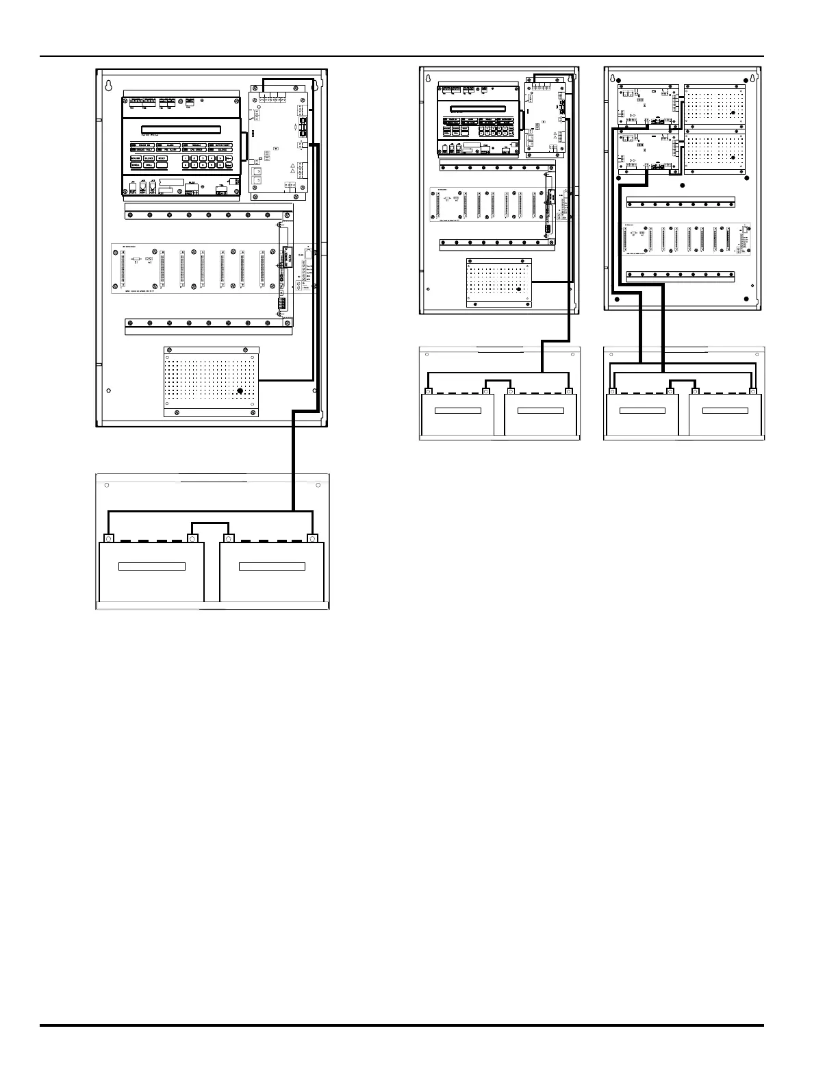
Figure B-3. System with Auxiliary Power Supply Module
Figure B-4 shows an expanded single-loop PEGAsys system
which contains two motherboard assemblies, three complete
power supply assemblies (24 Amps of 24 VDC power), and up
to 16 total possible I/O modules. The I/O bus interconnections
between the two motherboards are done using 6 conductors
from the I/O bus terminal block on the motherboard in the main
enclosure to connect to the same terminal block on the
motherboard in the expansion enclosure. This connection al-
lows complete supervision of all I/O modules installed on the
second motherboard by the CCM in the main enclosure. 24 VDC
power for the motherboard in the expansion enclosure would
derive from one of the power supply assemblies installed in that
enclosure. A simple two-wire connection is all that would be
required.
The power supplies need to be tied to the I/O bus for communi-
cations purposes. To accomplish this in the above example, the
installer would use a two conductor cable to connect the RX/TX
of the I/O bus from the motherboard assembly to the power sup-
ply. The second power supply could then be daisy chained to
the first to complete the communications connections.
Auxiliary power supplies in the expansion enclosure can share
a set of batteries or could support their own set of batteries
separately.
06-129562-001
NO
NC
R
S
4
8
5
A
B
C
C
M
M
O
T
H
E
R
B
D
S
Y
S
T
E
M
P
O
W
E
R
2
4
V
R
E
T
2
4
V
R
E
T
24V
RET
24V
24V
RET
RET
24V
RET
B
A
T
+
-
AUX1
AUX2
D
C
IN
2
C
DCIN 1
ACOUT
N
1
L
2
N GL N
ACIN
2
4
V
L
S
H
R
R
E
T
SHR
T
P
4
T
P
3
DS1
S3
T
B
9
T
B
8
R
R
2
1
1
2
S1
A
S
H
L
A
N
D
,
M
A
0
1
7
2
1
K
ID
D
E
-F
E
N
W
A
L
,
IN
C
.
RET
T
B
L
R
E
L
A
Y
T
B
L
R
E
L
A
Y
W
2
W
3
W4
F
1
W
1
S2
0
6
-
1
2
9
5
6
2
-
0
0
1
N
O
N
C
RS485
A
B
CCMMOTHER BD
SYSTEMPOWER
24V
RET
24V
RET
2
4
V
R
E
T
2
4
V
2
4
V
R
E
T
R
E
T
2
4
V
R
E
T
BAT
+
-
A
U
X
1
A
U
X
2
DCIN 2
C
D
C
IN
1
A
C
O
U
T
N
1
L
2
N
G
L
N
A
C
IN
24V
L
SHR
RET
S
H
R
TP4TP3
D
S
1
S
3
TB9TB8
R
R
2
1
1
2
S
1
ASHLAND,MA 01721
KIDDE-FENWAL,INC.
R
E
T
TBLRELAY
TBLRELAY
W2 W3
W
4
F1
W1
S
2
0
6
-1
2
9
5
6
2
-
0
0
1
N
O
N
C
RS485
A
B
CCMMOTHER BD
SYSTEMPOWER
24V
RET
24V
RET
2
4
V
R
E
T
2
4
V
2
4
V
R
E
T
R
E
T
2
4
V
R
E
T
BAT
+
-
A
U
X
1
A
U
X
2
DCIN 2
C
D
C
I
N
1
A
C
O
U
T
N
1
L
2
N
G
L
N
A
C
I
N
24V
L
SHR
RET
S
H
R
TP4TP3
D
S
1
S
3
TB9TB8
R
R
2
1
1
2
S
1
ASHLAND,MA 01721
KIDDE-FENWAL,INC.
R
E
T
TBLRELAY
TBLRELAY
W2 W3
W
4
F1
W1
S
2
PEGAsysKIDDE
Figure B-4. Expanded Single Loop System
Figure B-5 shows an expanded PEGAsys system which is ca-
pable of having 8 I/O modules of various types and a maximum
24VDC power at 40 amps. This DC power would be hardwired
into signal and release modules whose loading would otherwise
cause more than 8 amps of 24 VDC current to be drawn from the
motherboard during activation.
The hardwire option allows the system installer to provide indi-
vidual modules with their own power source. Refer to the particu-
lar modules installation diagram in Chapter 7 and Appendix A for
power-supply expansion guidelines.