August 199976-100016-001
Intelligent Suppression Control/Fire Alarm System
PEGAsys
3-3
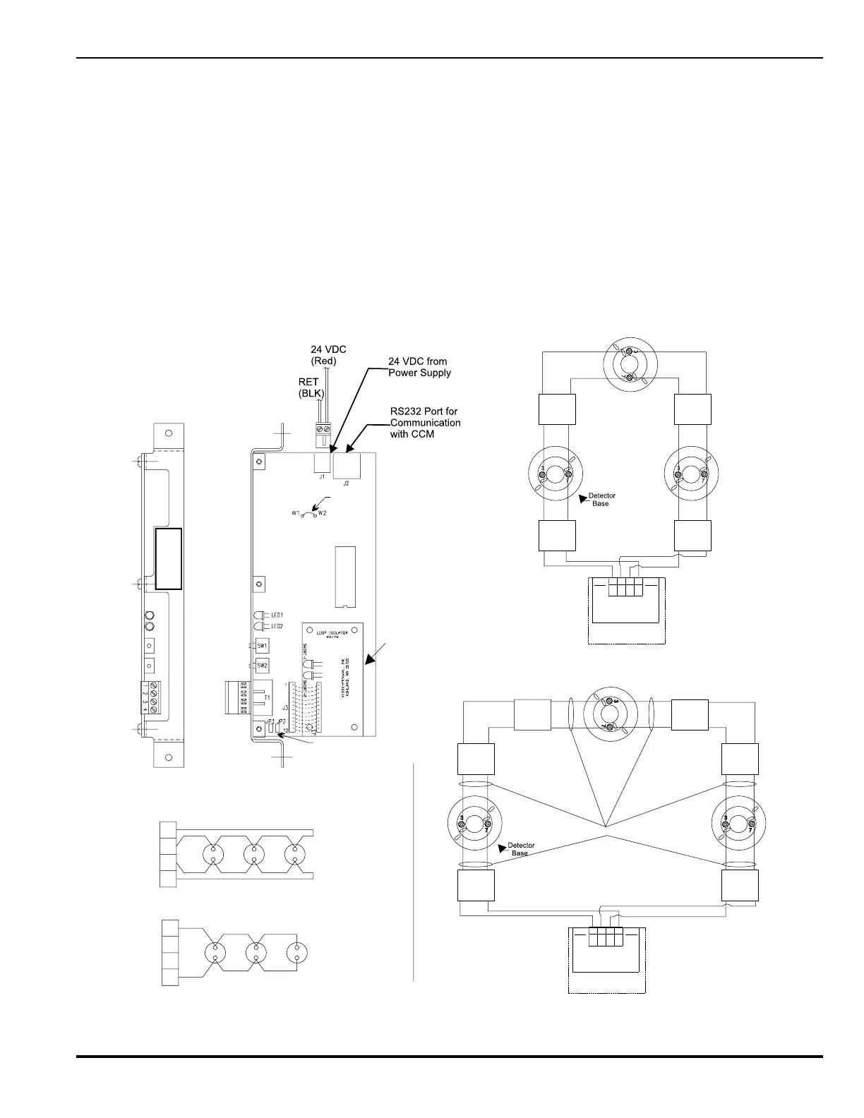
Figure 3-4. Receiver/Transmitter Module, Details
1
2
3
4
4
2
3
1
STYLE 6 Signal Line Circuit
STYLE 4 Signal Line Circuit
74-200012-001
Mounted to RX/TX
LOOP ISOLATOR
4321
24V
24V
RET
RET
RX/TX
NOTE: Adjacent loop isolators must be within 20ft. Of a device with wiring in conduit
to be in accordance with NFPA Style 7 requirements.
CPU Reset
PC Line Normal
CPU Reset
PC Line Reset
Loop Isolator
for Style 7
(74-200012-001)
See Note
See Note
Loop
Isolator
Zone 1
Zone 2
Zone 3
Loop
Isolator
Loop
Isolator
Loop
Isolator
Note: Each zone can consist of 30 loop devices
between loop isolators
74-200012-001
Mounted to RX/TX
LOOP ISOLATOR
4321
24V
24V
RET
RET
RX/TX
Loop
Isolator
Zone 1
Zone 2
Zone 3
Loop
Isolator
Loop
Isolator
Loop
Isolator
See Note
Loop
Isolator
Loop
Isolator
Note: Refer to jumper table on Dwg. 06-235371-002 in appendix I
STYLE 6 Signal Line Circuit, with Loop Isolator
STYLE 7 Signal Line Circuit
RX/TX
76-100005-001
3-3.2 Receiver/Transmitter Module (RX/TX)
The RX/TX functions as the hardware & software interface be-
tween the loop devices and the CCM. Each installed RX/TX
module continually monitors all addressable devices for alarm
and trouble conditions. Each device is capable of initiating and
sending alarm and trouble messages to the RX/TX module to
which it is connected.
The RX/TX receives control requests from the CCM and estab-
lishes communications with the loop devices. The RX/TX re-
ceives status changes from the loop devices and reports these
changes to the CCM. The RX/TX shown in Figure 3-4 is ca-
pable of communicating with up to 255 intelligent devices and
complies with the Signaling Line Circuit (SLC) requirements of
NFPA-72 Style 4, 6 & 7. Style 4 initiation circuit wiring will per-
mit “T” tapping or branch circuitry. Style 7 requires the use of
optional loop isolator devices.