August 199976-100016-001
Intelligent Suppression Control/Fire Alarm System
PEGAsys
3-1
CHAPTER 3
FUNCTIONAL DESCRIPTION
3-1 INTRODUCTION
This chapter provides a functional description of the devices/
modules used in the PEGAsys system configuration. Each func-
tional description covers one of the blocks shown in the overall
block diagram, Figure3-1.
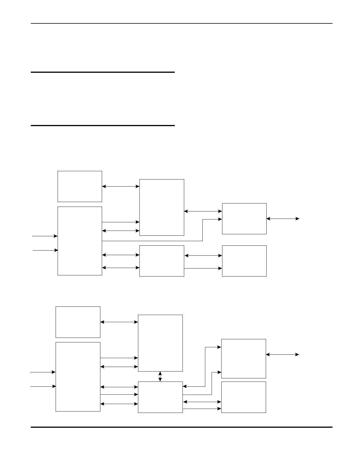
3-2 BLOCK DIAGRAM
The PEGAsys system is divided into seven functional blocks as
follows:
Figure 3-1. Overall Block Diagram, Single-Loop System
• Central Control Module
• Display Module
• RX/TX Module
• I/O Module
• RCUs (Field Devices)
• Power Supply Module
As described in Paragraph 1-1.2, the system comes in two con-
figurations the single-loop system and multi-loop system. The
above devices/modules for both configurations are shown in
the Overall Functional Block Diagrams, Figures 3-1 and 3-2.
Each device/module is described in detail in Paragraph 3-3.
Figure 3-2. Overall Block Diagram, Multi-Loop System
Display
Module
Power
Supply
Central
Control
Module
Optional
I/O
Motherboard
Optional
I/O Module
Receiver/
Transmitter
Module
(RX/TX)
RCU's
(Field Devices)
AC Line
Battery
Backup
24 VDC
24 VDC
24 VDC
I/O Bus
I/O Bus
RX/TX CCM
Comm
I/O Bus
24 VDC
Power/Comm
Line
Display
Module
Power
Supply
Central
Control
Module
Multi-Loop I/O
Motherboard
Optional
I/O Module
Receiver/
Transmitter
Module
(RX/TX)
Up to 8 RX/TX
Modules
RCU's
(Field Devices)
AC Line
Battery
Backup
RX/TX 24 VDC
24 VDC
I/O Bus
I/O Bus
RX/TX CCM
Comm
I/O Bus
24 VDC
Power/Comm
Line
RX/TX CCM
Comm
24 VDC
24 VDC