PAS SERIES Before Using the Unit 2-9
• SHUT (Shutdown)
The OUTPUT or the POWER switch can be turned OFF by applying
a shutdown
signal to the J1 connector on the rear panel. If the shut-
down signal is applied when CONFIG is set to OUTPUT OFF, the
voltage display shows "SHUT."
For details, see "4.1.7 Controlling the Output Shutdown Using Exter-
nal Contact".
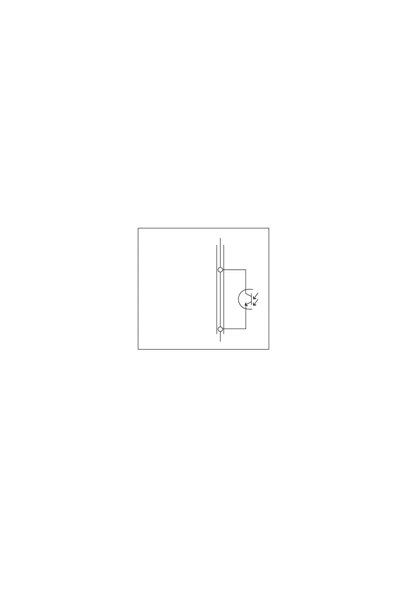
■ Alar
m Signal
Since the alarm signal output uses an open-col
lector photocoupler, it
is isolated from other terminals.
Maximum voltage: 30 V
Maximum current: 8 mA
Fig.2-9 ALARM signal
20
17
J1 connector
ALARM STATUS
ALARM COMMON
Inside
the unit
 Loading...