PAS SERIES Parallel and Series Operation 5-5
5.1.3 Load Connection for Series Operation
• When you are done with the connection, be sure to
attach the output terminal cover to prevent the possi-
bility of electric shock.
• Securely connect the protective conductor terminal of
t
he unit
.
• Take measures to securely connect the load cable to
the terminals such as by using crimp terminals.
Connection procedure
1. Check that the POWER switch is off on all power supply
un
its to be connected in series.
2. Remove the output terminal cover.
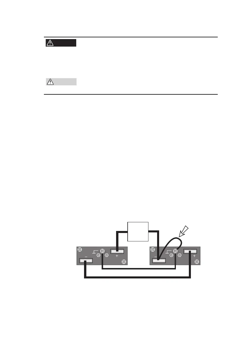
3. Connect the load cable and chassis cable as shown in
Fig.5-3.
Connect one of either the - (neg.) terminal or the + (pos.) terminal
of the master or slave unit to the chassis terminal.
Wire the load cables connecting the power supply units as thick
and as short as possible. If the voltage drop in the output cable is
large, the difference in potential between power supply units and
load fluctuations becomes large.
Refer to "3.3 Connecting the Load" and select a load cable with
sufficient current capacity.
4. Attach the output terminal cover.
Fig.5-3 Load Connection for Series Operation
(Example in which the - (neg.) terminal of the
ma
ster
unit is connected to the chassis terminal)
Slave unit Master unit
Load
Thick and short