PAS SERIES Parallel and Series Operation 5-11
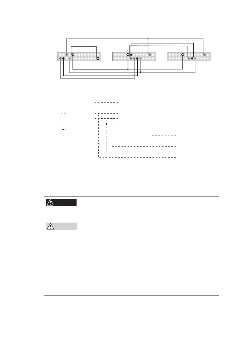
Fig.5-6 Connection for parallel operation
5.2.3 Load Connection for Parallel Operation
• When you are done with the connection, be sure to
attach the output terminal cover to prevent the possi-
bility of electric shock.
• When connecting the output terminal to the chassis
terminal, be sure that the output terminal of the same
polari
ty (+ or -) for each unit is connected to the chas-
sis terminal. If you connect the output terminal of dif-
ferent polarities for each unit, the output is short-
circuit
ed
through the GND cable of the AC power
cord. This will result in failure to obtain proper outputs
and will burn the cable connected to the chassis.
• Take measures to securely connect the load cable to
the terminals such as by using crimp terminals.
Master unit
PRL OUT
+
24
PRL OUT
– 26
[PRL COMP OUT]
STATUS COM 17
ALM STATUS 20
OUTON STATUS 21
D COM 2
Slave unit1
Slave unit2
12 PRL IN
+
14 PRL IN –
[PRL COMP IN]
17 STATUS COM
10 SHUT DOWN
3 OUT ON/OFF CON
15 NEXT PRL OUT
+
16 NEXT PRL OUT –
[NEXT PRL COMP OUT]
12 PRL IN
+
14 PRL IN –
[PRL COMP IN]
10 SHUT DOWN
3 OUT ON/OFF CON
17 STATUS COM
[ ] in case of 160 V, 320 V and 500 V models.