5-12 Parallel and Series Operation PAS SERIES
Connection procedure
1. Check that the POWER switch is off on all po
wer supply
units to be connected in parallel.
2. Remove the output terminal cover.
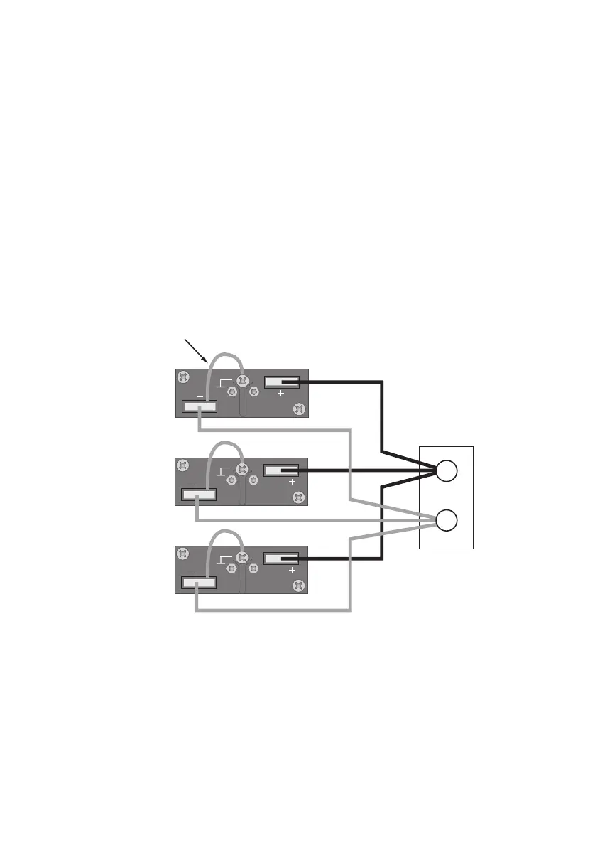
3. Connect the cables as shown in Fig.5-7.
Refer to "3.3 Connecting the Load" and select a load cable with
sufficient current capacity. In addition, use the shortest load cables
of the same length and cross-sectional area from each power sup-
ply to the load.
Wire the signal cable of the J1 connector and load cables as far
apart as possible.
4. Attach the output terminal cover.
Fig.5-7 Load Connection for Parallel Operation
Load or relay
terminal board
When connecting the - (neg.)
terminal to the chassis terminal
−
+
 Loading...