PAS SERIES Basic Operation 3-15
3.3.2 Connecting to the Output Terminals
• Possible electric shock. Be sure to turn the POWER
switch off before touching the output terminal on the
rear panel. Be sure to attach the OUTPUT terminal
cover after wiring the load.
The chassis connection wire is not included. If you are using the chas-
sis connection wire that comes with the analog remote control con-
n
ector kit (OP01-PAS), you can use it immediately as it is already
assemb
led.
1. Turn the POWER switch off.
2. Conne
ct the chassis terminal to either the - (neg.) or +
(pos.) output terminal using the chassis connection wire.
The output terminal has an M3 hole used to connect the chassis
connection wire.
If you are not using the optional OP01-PAS, attach a crimping
terminal to a wire of AWG18 or higher to make the connection.
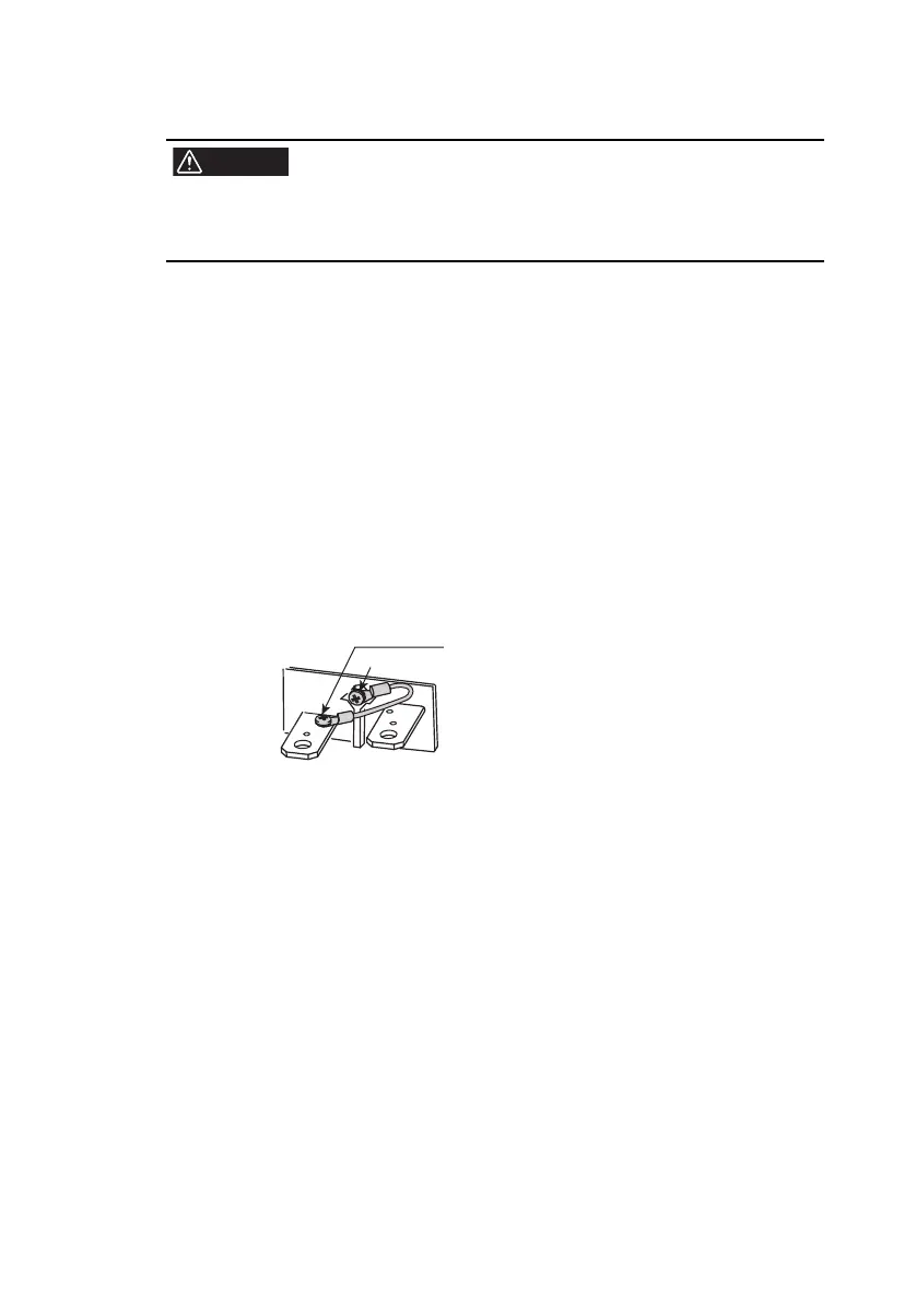
Fig.3-3 Connection of the chassis connection wire
(e
xample in which the - (ne
g.) output terminal is
connected)
3. Attach cr
imping term
inals to the load wires.
The output terminal on the rear panel has M4- (with taps) and M8-
sized holes for connecting the load wires. Attach the crimping
terminal that matches the screws.
Use crimping terminals that are less than equal to 5.5 mm
2
with
the M4-sized holes.
This M3 screw is fastened to the + (pos.)
terminal before factory shipment. If you want
to connect the chassis connection wire to the
- (neg.) output terminal as shown in the
gure, change it as such.
M3 screw