4-2 Remote Control PAS SERIES
4.1.1 About the J1 Connector
• The J1 connector contains pins that are at the same
electric potential as the output terminal. If you are not
using the J1 connector, to prevent the possibility of
electric shock, be sure to insert the protective socket
provided.
• To prevent the possibility of electric shock, be sure to
use the protective cover on the sockets.
The connector parts needed to connect the J1 connector (standard
MIL connector) are not provided. table 4-1 shows the tools an parts
that are needed.
For information on how to obtain the tools and parts, contact your
Kikusui agent or distributor.
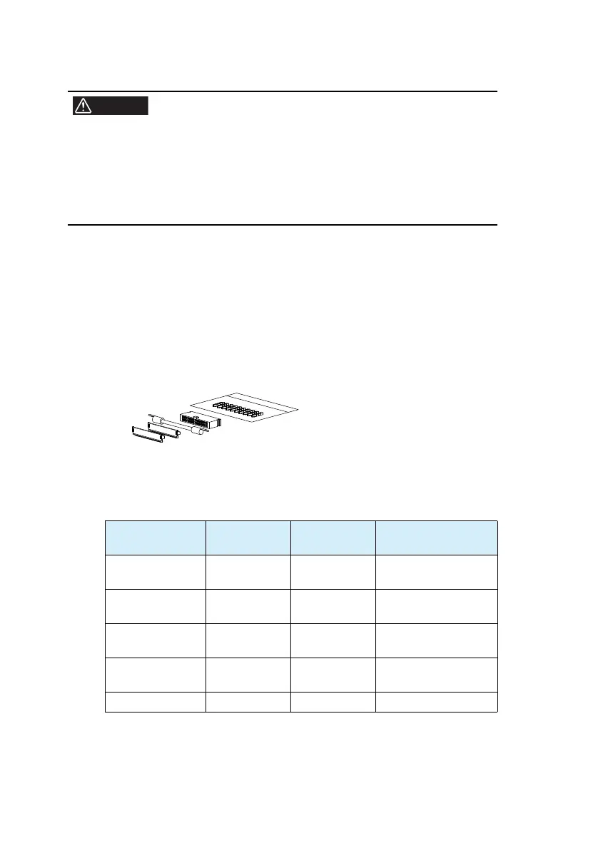
An optional OP01-PAS Analog Remote Control Connector Kit is
available for making the connection.
Fig.4-1 OP01-PAS
Table 4-1 Connector parts by Omron needed to connect the
J1 connector
For details on how to use the tools, read the catalog by Omron.
Product Model
Kikusui Parts
No.
Notes
Single contact
connection tool
XY2B-7006 Y2
-070-001
–
Contact removal
tool
XY2E-0001 Y2-070-002
–
Pin (contact)
XG5W
-0031 84-49-0100
Recommended wire
size A
WG24 (UL-1061)
Socket
XG5M-2632-N 84-49-0160
MIL standard type
socket
Pr
otection cover XG5S-1301 84-49-0161 –