4-22 Remote Control PAS SERIES
4.2.2 External Monitoring of the Operation Mode
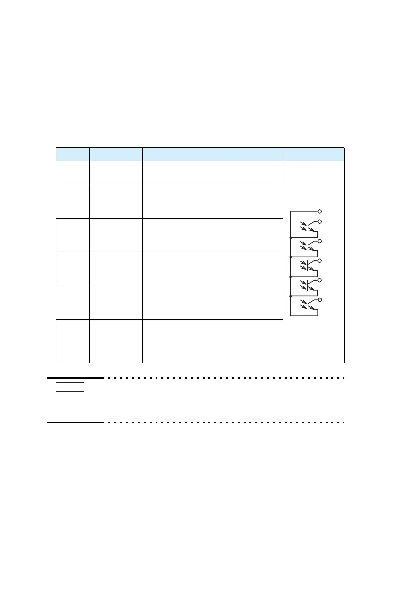
The J1 connector consists of status outputs that can be used to exter-
nally monitor the operating condition of the unit. The status outputs
consist of the following five items.
The outputs are open collector outputs of photocouplers; they are
insulated from the internal circuits of the unit.
Table 4-4 Status output
• Maximum rating of each signal terminal
Maximum applied voltage (to a single pin) of 30 V and max-
imum current of 8 mA
Pin No. Signal Name Description Circuit
17
STATUS
COM
Common for status output
Photocoupler
emitter output
18 CV ST
ATUS
Set to low level when in constant voltage
mode.
Phot
ocoupler collector output
19 CC STATUS
Set to low level when in constant current
mo
de.
Phot
ocoupler collector output
20
ALM
ST
AT
US
Set to low level when a protection func-
tion is activ
ated.
Photocoupler collector output
21
OUTON
ST
AT
US
Set to low level when OUTPUT is turned
off.
Pho
tocoupler collector output
22
PWR OFF
ST
AT
US
Output a low level signal for approxi-
mately 0.5 s when the POWER switch
turned of
f.
Photocoupler collector output
NOTE