4-6 Remote Control PAS SERIES
• Make sure the polarity of Vext is correct. Otherwise,
damage to the unit may result.
• Do not apply voltage or reverse voltage exceeding
10.5 V across the external voltage control pins. Oth-
erwise, damage to the unit may result.
• The input impedance across the external voltage control pins
is approximately 30 kΩ.
• Use a low-noise and stable voltage source for Vext. The noise
in V
ext is multiplied by the amplification factor of the unit
and appears at the unit's output. Thus, the output ripple noise
may not meet the unit's specifications.
• To minimize the influence of no
is
e on the output, use a 2-
core shielded wire or a twisted-pair wire to connect the con-
trol terminals and Vext. Make the wires
as short as possible.
Susceptibility to the effects of noise increases as the wires
get longer
. When wires are long, proper operation may be
hindered even if a cable with anti-noise measures is used.
When using a shielded
cable, connect the
shield to the -
(neg.) output terminal. If the shield needs to be connected to
the Vext side, see next page " Connecting the Shield to the
Vext Side".
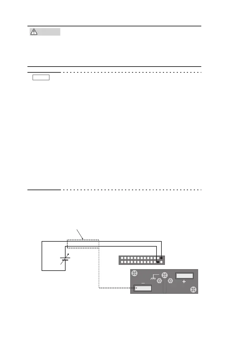
■ External voltage source (Vext) connection
Pins 1 and 4 of th
e J1 connector are used.
Fig.4-1 Connection of the output voltage control using
e
xte
rnal voltage
NOTE
J1
125
24
13
1426
2-core shielded or
twisted-pair wire
Vext
+
–
 Loading...