M0188-01Model 3000
6-24 Rev. 6/11
TM
KPM II Monitor Operation
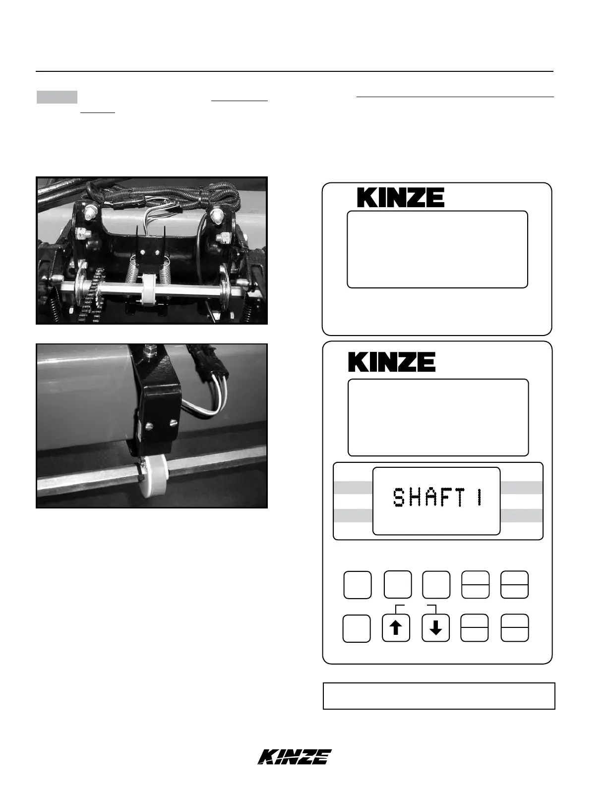
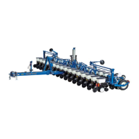
STEP 6 If the monitor system includes shaft rotation
sensors, these should be installed at this
time. Plug in the L.H. shaft first, then the
R.H. shaft. L.H. and R.H. is determined
by facing in the direction the machine will
travel when in use.
“LSHAFT” or “SHAFT 1” will display on
the lower LCD when the first shaft rotation
sensor is installed. “RSHAFT” or “SHAFT 2”
will display when the second shaft rotation
sensor is installed.
01189906
D12140713
NOTE: SMM console may not be applicable to
all models.
12060211
SMM
ON
AREA
OFFEXIT
ENTER
OK
CLEAR
SETUP
ROW
SPACING
TOTAL
AREA
UNITS
SPEED
VOLUME
SCAN
SEED
POPULATION
SEED
SPACING
FIELD
AREA
SPACING
TOTAL
SEED
POP.
FIELD
SELECT
SPEED
SCAN
SETUP
SETUP
REAR
1
REAR
1211109876543(2 13 14 15 16 1718)
(FRONT)
FLASHING
KPM II
•
NOTE: Illustrated using rear/front configuration.
The KPM II Stack-Mode console shows LEFT in
the left/right configuration, REAR in the rear/front
configuration and FRONT LEFT/REAR LEFT in
the four sections configuration.


 To Next Page