FlexStat 11 Operation Guide, Rev. R
(Advanced) CO
2
Sensor (and DCV)
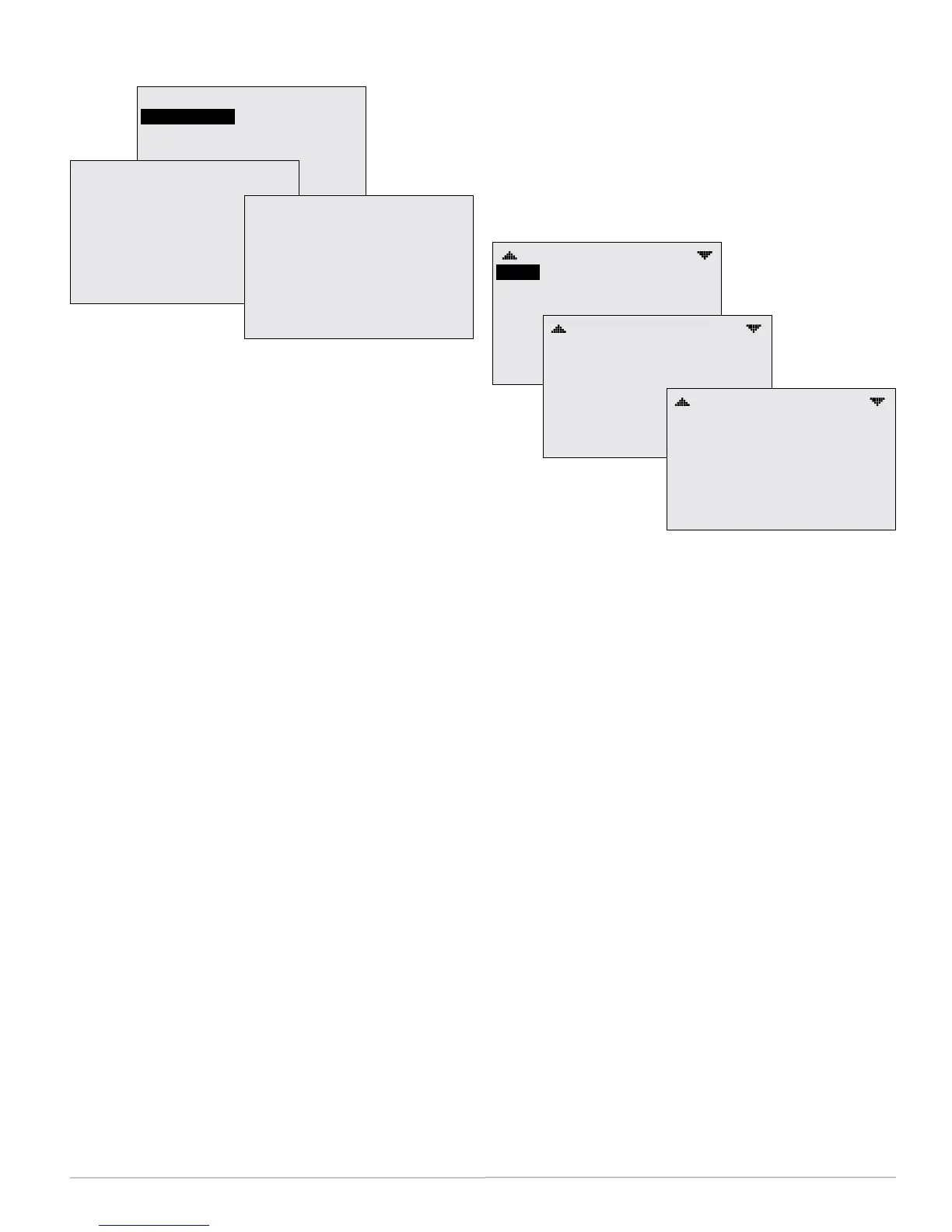
CO2 SENSOR
SENSOR INFO
CALIBRATION
CO2 SENSOR INFO
MODEL: T6615
SUB VOL: A15
SW DATE: 090217
S/N: AB00011759
CO2: 873
ELEVATION: 0
STATUS: NORMAL
CO2 CALIBRATION
ELEVATION: 0
REFERENCE GAS: 300
MODE: MONITOR
CO2: 1067
STATUS: NORMAL
CAL TIME: 00:00
CO
2
Sensor Setup and Information
NOTE: Set the desired CO
2
setpoint under the
Setpoints menu. See Setpoints on page 25.
For maximum sensor accuracy, enter the elevation
(altitude)abovesealevel of the building’s location.
(The default value is 0.) Elevation for any particular
location can be found at such sources as www.earth-
tools.org. (For very tall buildings, the upper oors
would have a higher elevation than lower oors.)
After power is rst applied or the FlexStat is restart-
ed, the sensor goes through a warm-upfor approxi-
mately half a minute. During the time the sensor
count will be 0 ppm and the Status line will display
WARMUP instead of NORMAL.
The sensoranditsrmware are identied by the
model, the compilation subvolume (SUB VOL), com-
pilation date (SW DATE in yymmdd format), and
serial number.
NOTE: With the CO
2
sensor enabled, a trend log is
automatically generated. See (Advanced)
Trend Logs on page 20.
The BAC-13xxxx models do not have a calibration
with gas option. It uses Automatic Background
Logic, or ABC Logic
™
, a patented self-calibration
technique designed to be used inapplicationswhere
concentrationswilldroptooutsideambientcondi-
tions(approximately400ppm)atleastthreetimes
ina14dayperiod, typically during unoccupied
periods.
The BAC-14xxxx models have a calibrationoption
forapplyinggastothesensor for maintaining maxi-
mum accuracy. These models have a dual channel
sensor (a CO
2
channel measures gas concentration,
and a reference channel measures the sensor signal
intensity). Self-calibrations are performed approxi-
mately every 24 hours using the reference channel.
During the self-calibration the sensor PPM reading is
frozen and will not react to changing CO
2
.
For instructionsoncalibratingthe BAC-14xxxx
models withgas, see the CO
2
Sensor Calibration sec-
tion in the FlexStatApplicationGuide.
DCV (Demand Control Ventilation) Setup
DAMPER SETUP
ECON:
DCV: ADVANCED
DCV SETUP
MIN POSITION: 0%
CNTRL (0–100%): 2–10 V
ECON ENBLE TEMP: 55° F
LOW LIMIT ALARM: 45° F
MODULATING
DCV SETUP
VENT MODE: STARTUP
DCV DAMPER SETUP
CO2 MAX (PPM): 1000
CO2 BASE (PPM): 400
OA AREA: 2%
OA FULL: 5%
OA MAX: 40%
DCV SETUP
OA PURGE: 0%
OA LOW VENT: 65°F
OA HIGH VENT: 80°F
FAN MAX OFF (MINS): 30
CLG DESIGN TEMP: 95°F
HTG DESIGN TEMP: 20°F
VENT OVRIDE (MINS): 30
The CO
2
sensor is used with DCV (Demand Control
Ventilation sequences to provide optimal ventila-
tion and energy savings for a space. When BAC-
12xxxx/13xxxx/14xxxx models have an application
with the CO
2
sensor AND a modulating economizer
option enabled, menu items for DCV (Demand Con-
trol Ventilation) will appear. Most DCV seings are
accessed from the Damper setup menu. See Damper
Setup on page 7, Setpoints on page 25, and DCV (De-
mand Control Ventilation) on page 24.
Although BAC-12xxxx FlexStats do not have a built-
in CO
2
sensor, they still have DCV control sequences
available. When DCV is enabled in the Damper
Setup menu of these models, IN9 is assumed to be
connected to an external SAE-10xx CO
2
(duct or
space) sensor. 0–5VDConthatinput (congured
in the (Advanced) Inputs menu)willmapto0–2000
ppm.TheoutputoftheconnectedSAE-10xxmust
alsobeconguredtomatchtheFlexStat’sinput (see
the installation guide for the appropriate SAE-10xx
model), and the FlexStat’s IN9 pull-upresistor must
be set for 0–12VDC (see the appropriate FlexStat
installation guide)! BAC-13xxxx/14xxxx FlexStats
also have the external sensor option, and if used, the
highest of the two readings (internal vs. external)
will be used to control DCV sequences. The CO
2
ppm
display (if enabled) also shows the highest of the two
levels. (Allow at least 15 minutes after installation for
the reading to stabilize.)