SECTION 3
OPERATION
July 2003
p 3-8
05132519
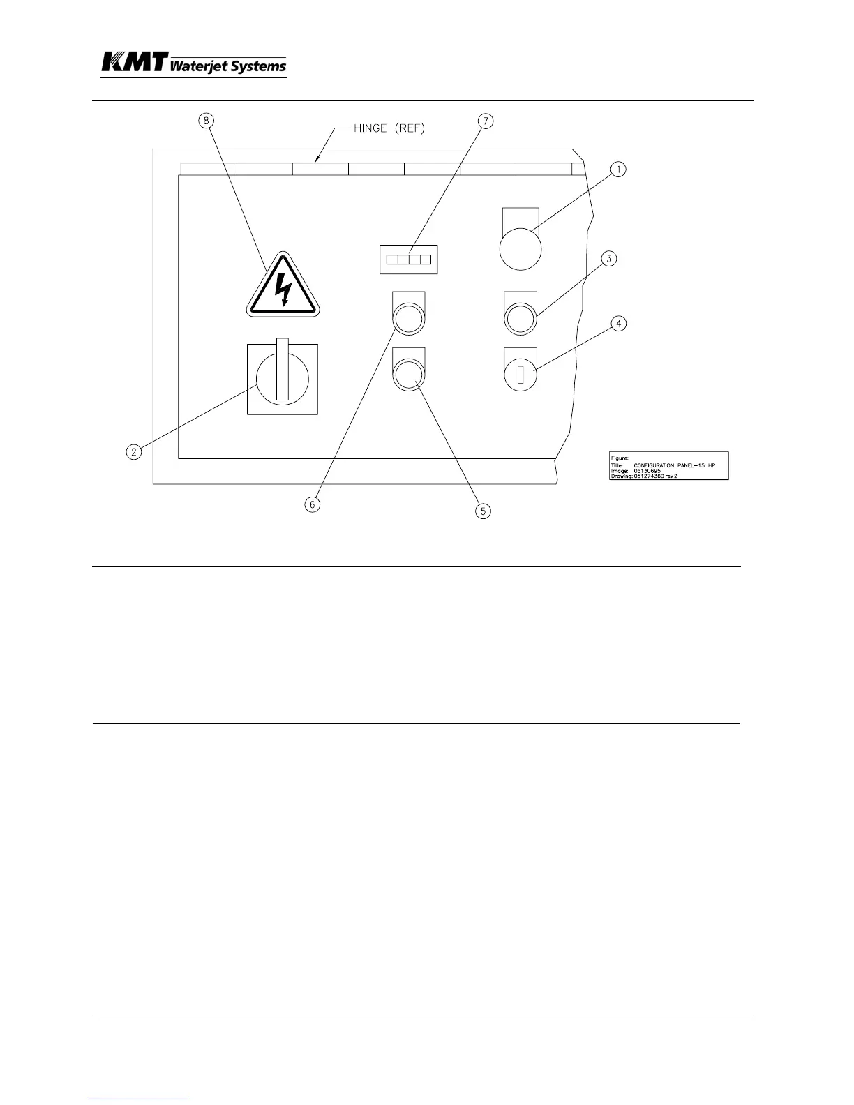
Item Description
1 Palmbutton – Emergency Stop
2 Handle – Electrical Disconnect
3 Pushbutton – (Control Power On—White Light)
4 Selector Switch-Local/Remote Control
5 Pushbutton – (Stop Pump/ Fault--Red Light)
6 Pushbutton – (Start Pump--Green Light)
7 Hourmeter
8 Decal—Shock Hazard
Pull out EMERGENCY STOP (E-STOP) palm button.
Press CONTROL POWER ON pushbutton to power up unit. The CONTROL
POWER ON pushbutton should be lit.
Press START pushbutton to start pump. The intensifier assembly will
stroke and stop when the HP lines are filled. The pump will maintain a
constant HP water signal even though the nozzle is closed and no water is
circulating. This is called standby or deadheaded condition.
3. Check for any leaks throughout the installation.
4. Remove front cover and locate the pump compensator adjustment screws.
Remove cover nut on INBOARD adjustment screw, and loosen jam nut.
Rotate 3 mm allen wrench clockwise to increase HP water signal,
counterclockwise to reduce HP water signal. Maximum pressure is limited

 Loading...