SECTION 8
ELECTRICAL SYSTEM
July 2003
p. 8-3
05130703
After pressing the START Pushbutton:
• The unloading valve delays hydraulic pressure build-up while the
motor starter circuit accelerates the motor to normal rotating speed.
• The intensifier assembly starts operating. Reversal position is sensed
by proximity switches, which send signals to the relay logic inside the
control panel. The relay logic activates the opposite solenoid on the
directional control valve.
8.2 Maintenance Overview
Electrical components require minimum attention and service.
8.2.1 Proximity Switch Service
If the pump quits pumping water, the proximity switch may need to be
replaced. Check the LED lights on the switch.
Symptoms of a failed proximity switch are (1) the LED lights do not
change state (indicating not sensing the piston) or (2) the LED lights are
continuously flashing. Replace the switch when failure occurs.
Recommended Tools:
Allen (hex) Wrench,
M5
Torque Wrench
Rags
Components:
(1) Intensifier
Assembly
(2) Electrical Harness
(3) Proximity Switch
(4) Hydraulic Cylinder
(5) Piston
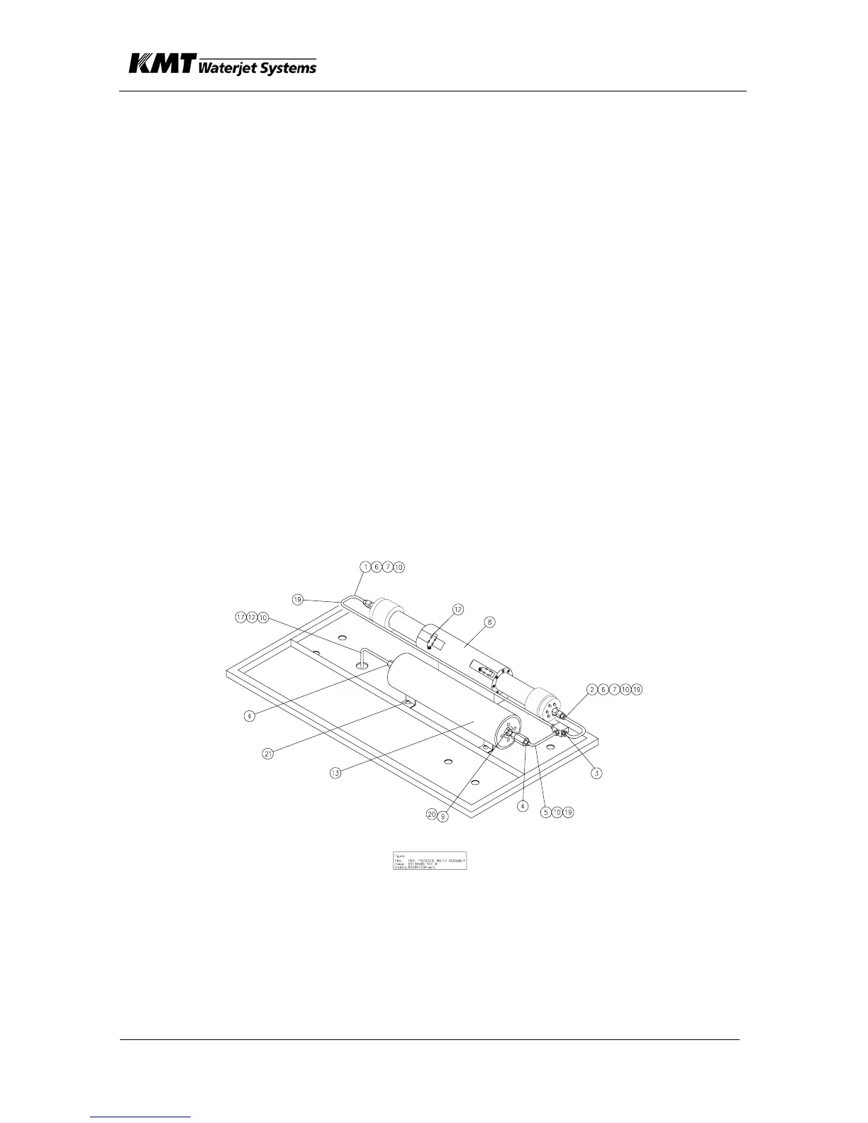
Parts:
Proximity Switch
1 HP Tube
2 HP Tube
3 Tee Fitting
4 HP Fitting
5 HP Tube
6
Gland Nut - HP
Tube
7 Collar - HP Tube
8 HP Intensifier
9 HP Fitting
10 Ferrule, .25 Hose
12 Proximity Switch
13 HP Attenuator
19 Conduit, Flexible
20 Enclosure End
21 Spacer

 Loading...