SECTION 7
HIGH PRESSURE WATER
Nov 2002
p. 7-21
05126826
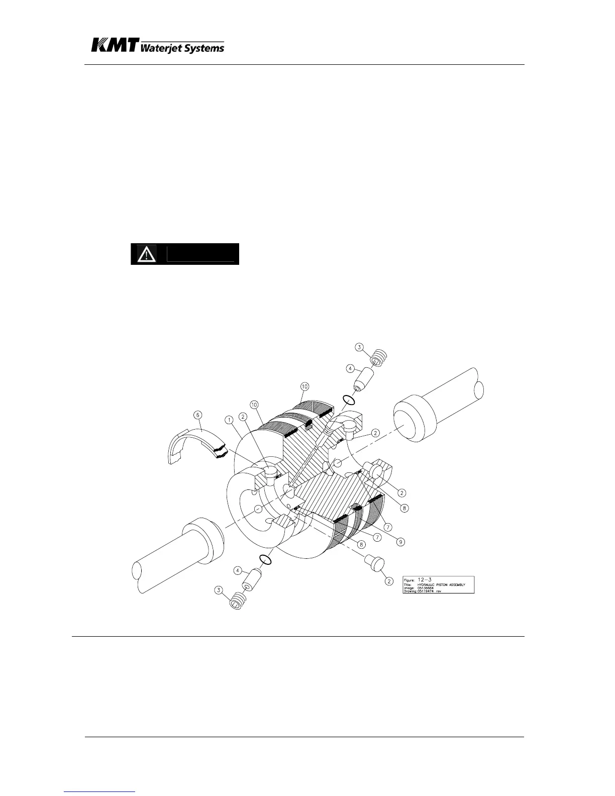
7.3.7 Hydraulic Piston
The hydraulic piston contains a seal assembly, bearing rings, pins and
flat spring bands, and check valves. Bearing rings (10) provide wear
contact between piston and cylinder ID. Plungers (12) are held in place
by 6 each pins (2) per plunger. Pins (2) are maintained in place by flat
steel band (6). Check valves (4) are mounted internal to the piston to
vent unwanted hydraulic pressure to the piston opposite side. These
check valves prevent hydraulic pressure from building behind the
plunger button
Replace Piston Seal
CAUTION
Do not scratch bottom surface of piston seal groove.
Scratches to the seal groove sides and/or bottom can
result in a hydraulic leak.
1. Remove bearing rings (10) and worn seal ring assembly (9).
NOTE: Use a smooth, dull-edged blade made from brass or similar soft
(relative to steel) material to remove and install seal assemblies.
Item Description
1. Piston
2. Pin (12 Each)
3. Set Screw (2 ea.)
4. Check Valve (2
ea.)
5. Threadlocking
Adhesive
6. Flat Wire Snap
Ring (2 ea.)
7. Backup Ring
(2 ea.)
8. O-ring
9. Seal Assy
10 Bearing Ring
(2 ea.)

 Loading...