9.7
Section 9
Disassembly
9
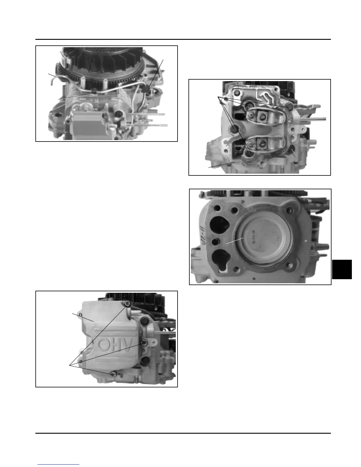
Figure 9-24. Removing Cylinder Head.
Figure 9-22. Removing Fuel Line (not on all
models).
Remove Valve Cover and Cylinder Head
1. Remove the remaining hex. flange mounting
screws and any loose spacers (stamped steel
covers) from the valve cover. Note their placement/
orientation. Remove the valve cover from the
cylinder head assembly. See Figure 9-23 and 9-24.
NOTE: The valve cover is sealed to the cylinder
head using RTV silicone sealant. When
removing valve cover, use care not to
damage the gasket surfaces of cover and
cylinder head. To break the RTV seal,
hold a block of wood against one of the
flat faces of the valve cover. Strike the
wood firmly with a mallet. If the seal
doesn’t break loose after 1 or 2 attempts,
repeat procedure on other side.
Fuel
Line
Rubber
Grommet
Hex. Flange
Screw
and Clip
Valve Cover
Hex. Flange
Screws
Hex. Flange
Screws
Cylinder
Head
Hex. Flange
Screw and
Spacer
Figure 9-23. Removing Valve Cover.
2. Remove the hex. flange screws, spacer (from the
screw between the intake and exhaust ports),
cylinder head, push rods, and cylinder head
gasket.
Cylinder Head Gasket
If the push rods will be reused, they should be
marked with a piece of tape ("I" or "E" at the time
of removal, so they are reinstalled in the same
location. See Figures 9-24 and 9-25.
Figure 9-25. Removing Cylinder Head Gasket.
Disassemble Cylinder Head
Two basic styles of heads are used. The first style
utilizes a rocker bridge configuration as shown in Figure
9-26. The second style contains separate rocker arm
assemblies (with or without a guide plate), and either a
non-adjustable or adjustable valve lash configuration.
Variations of this style are shown in Figure 9-27.
Components are unique to each head configuration.
Follow the appropriate procedure based upon the
configuration involved.
NOTE: Before disassembly, determine the specific
head configuration involved, and mark all valve
train components to assure they are
reassembled on same side.
1. Remove the spark plug. See Figure 9-26.
 Loading...