9.12
Section 9
Disassembly
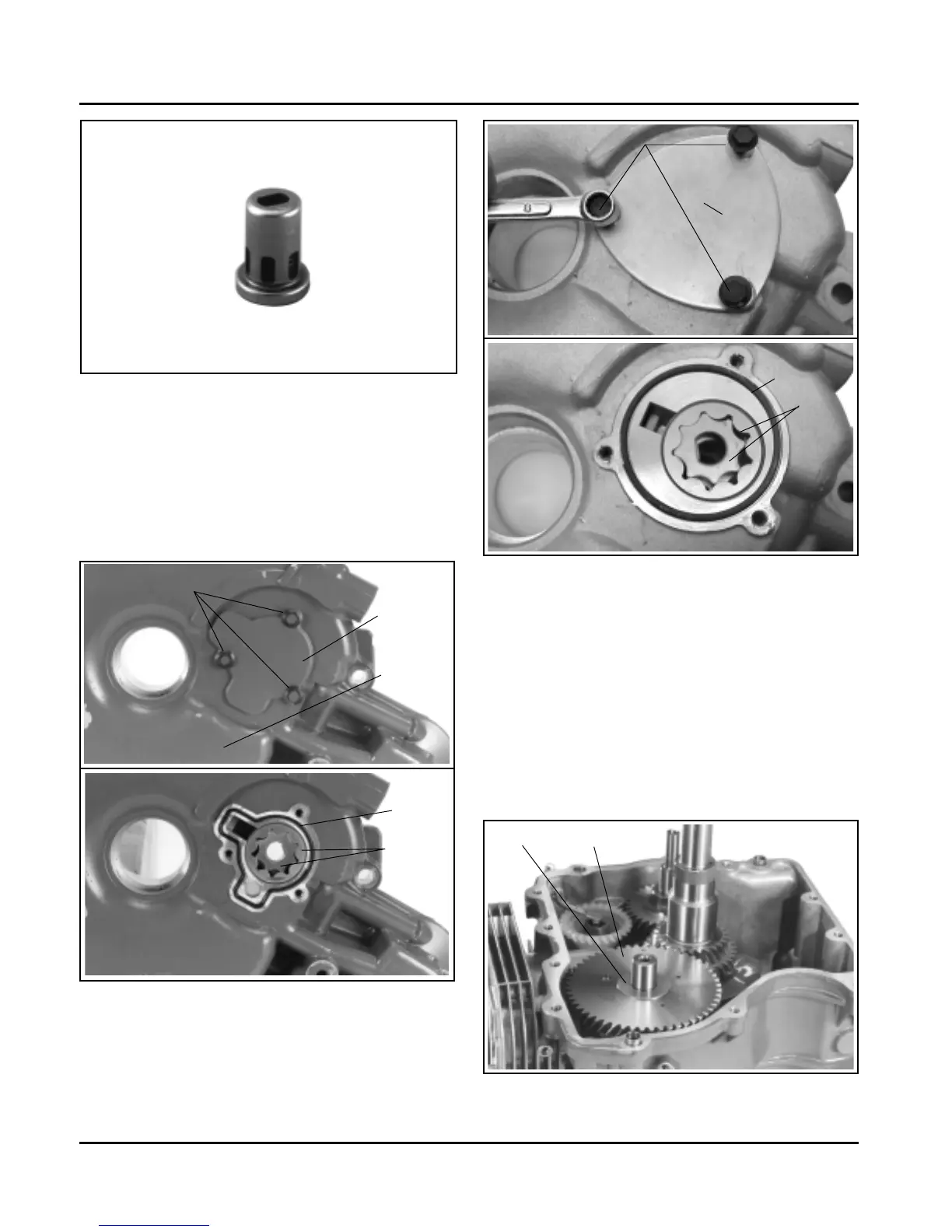
Figure 9-42. Original Style - Removing Oil Pump
Covers and Rotors.
Shim
Camshaft
Oil Pump Cover
Hex. Flange Screws
O-Ring
Oil
Pump
Rotors
Figure 9-43. New Style - Removing Oil Pump
Covers and Rotors.
Remove Hydraulic Lifters and Camshaft
1. From the cylinder head side, pull lifters out of their
bores with the lifters tool (see Section 2).
2. Mark or identify the hydraulic lifters as either
intake or exhaust. The exhaust lifter is nearest to
the PTO side of the crankcase.
3. Remove the camshaft and shim (not on all
models). See Figure 9-44.
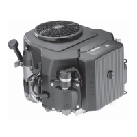
Figure 9-41. Later Style - Oil Pressure Relief Valve.
NOTE: Later one-piece relief valves (Figure 9-41) are
staked in place and do not require removal,
unless replacement is necessary.
4. Remove the three hex. flange screws, oil pump
cover, O-Ring, and oil pump rotors. See Figures
9-42 and 9-43.
Oil Pan
Hex. Flange Screws
Oil Pump
Cover
O-Ring
Oil
Pump
Rotors
Figure 9-44. Removing Camshaft.
 Loading...