11.16
Section 11
Reassembly
Install Ignition Module
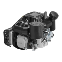
1. Rotate the flywheel so the magnet is away from the
ignition module bosses. Install the ignition module
to the bosses on crankcase, using the hex. flange
screws. The directional arrow (on some modules)
denoting proper flywheel rotation must be up. Move
the module as far from the flywheel/magnet as
possible. Tighten the hex. flange screws slightly.
2. Insert a 0.25 mm (0.010 in.) flat feeler gauge or
shim stock between the magnet and ignition
module. See Figure 11-48. Loosen the screws so
the magnet pulls the module against the feeler
gauge.
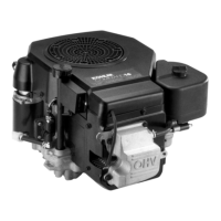
Figure 11-50. Installing Starter Side Cylinder Baffle
(not on all models).
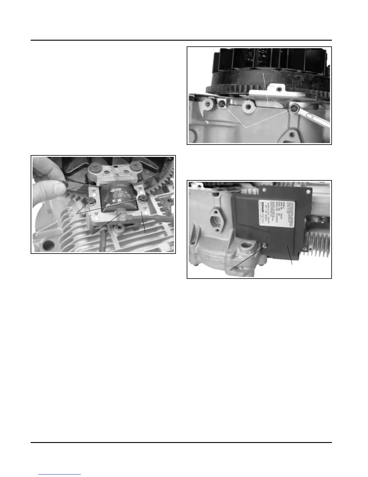
3. Install gasket and heat deflector to the intake
studs. Place the carburetor side cylinder baffle in
position and attach with the one hex. flange
screw. Temporarily install the silver screw if the
screw also attaches the fuel solenoid ground lead.
See Figure 11-51.
Figure 11-49. Installing Blower Housing Back Plate.
2. Install the starter side cylinder barrel baffle and
one hex. flange screw. See Figure 11-50.
Hex. Flange
Screws
Flat Feeler
Gauge
Kill Lead
Ignition Module
Magnet
Figure 11-48. Installing Ignition Module.
3. Tighten the hex. flange screws as follows:
Into new as-cast hole–6.2 N·m (55 in. lb.).
Into used hole–4.0 N·m (35 in. lb.).
4. Rotate the flywheel back and forth; check to make
sure the magnet does not strike the module.
Check the gap with feeler gauge and readjust if
necessary.
Final Air Gap: 0.203/0.305 mm (0.008/0.012 in.).
5. Connect the kill lead to the tab terminal on the
ignition module.
Install Baffles and Blower Housing
NOTE: Leave all hardware slightly loose until all
sheet metal pieces are in position.
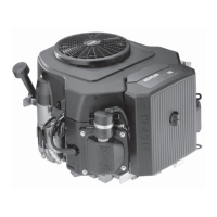
1. Install the blower housing back plate and two hex.
flange screws. See Figure 11-49.
Hex. Flange Screw
Cylinder Barrel Baffle
(Starter Side)
Hex. Flange Screws
Blower Housing Back Plate
 Loading...