TP-6714 4/1090 Section 5 Setup
6446
12
6
1
7
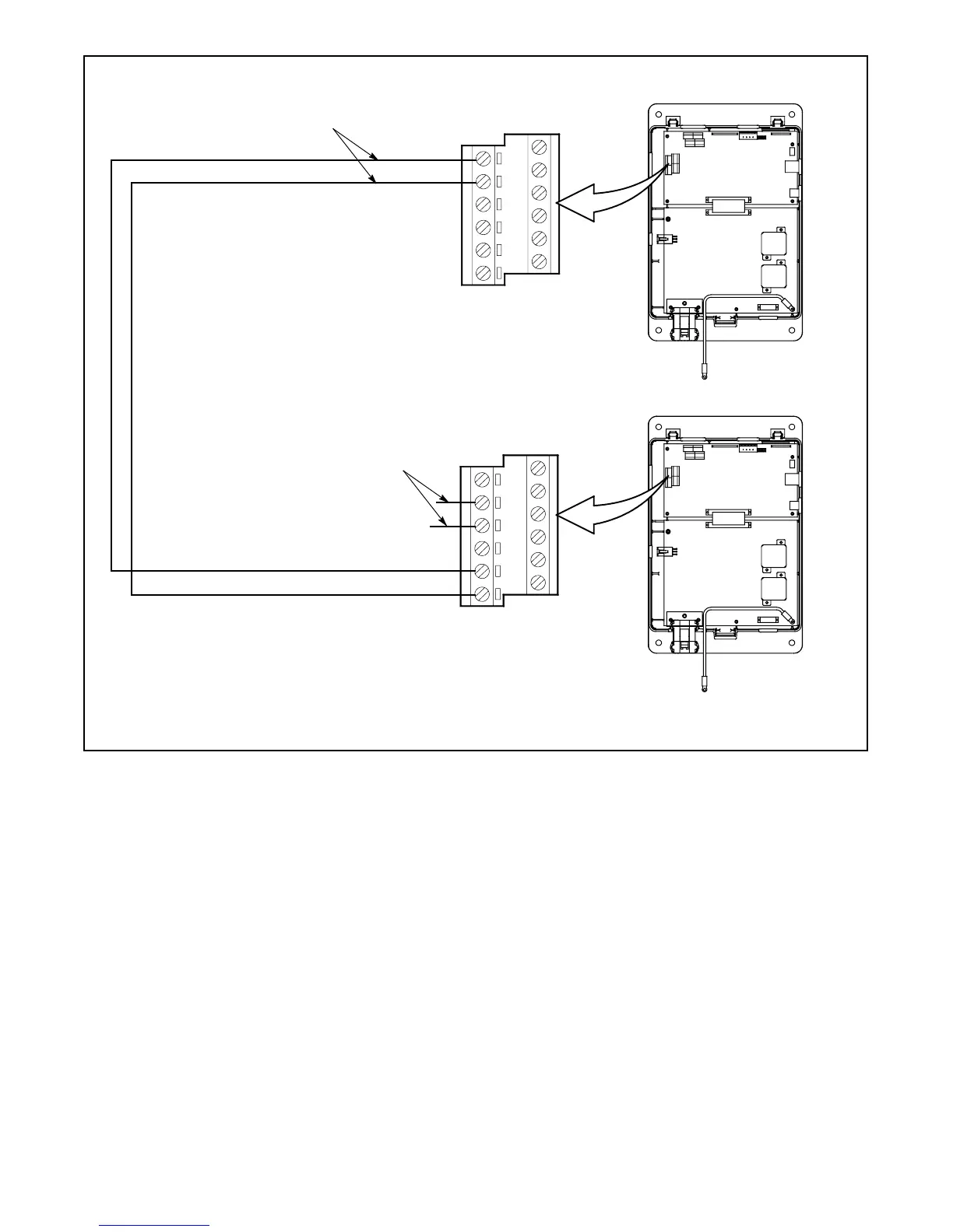
ATS1
ATS2
Connect Output 1 terminals
TB1-5 and TB1-6 on ATS 1 to
Input 1 terminals TB1-1 and
TB1-2onATS2.
Assign ATS 1 main logic board
output 1 to 3 Source System
Disable.
Assign ATS2 main logic board
input 1 to 3 Source System
Disable.
Connect one normally closed
output from ATS2 to G1 engine
start (ES) connections. Assign to
Engine Start Source N.
12
6
1
7
ATS2 TB1
on logic board
ATS1 TB1
on logic board
G1 ES
3 Source System Disable
Connect the ATS2 engine start contacts (on
the contactor or the field-connection terminal
block) to G2 engine start (ES) connections.
See Figure 5-27.
Figure 5-28 Input and Output Connections for Three-Source Systems

 Loading...


