S700 Safety Guide | 2 English
2.6 Electrical Installation
For connector overview (➜ # 192). For more interface pinout refer to the Instructions
Manual.
2.6.1 Important Notes
Only professional staff who are qualified in electrical engineering are allowed to install the
drive. Wires with color green with one or more yellow stripes must not be used other than for
protective earth (PE) wiring.
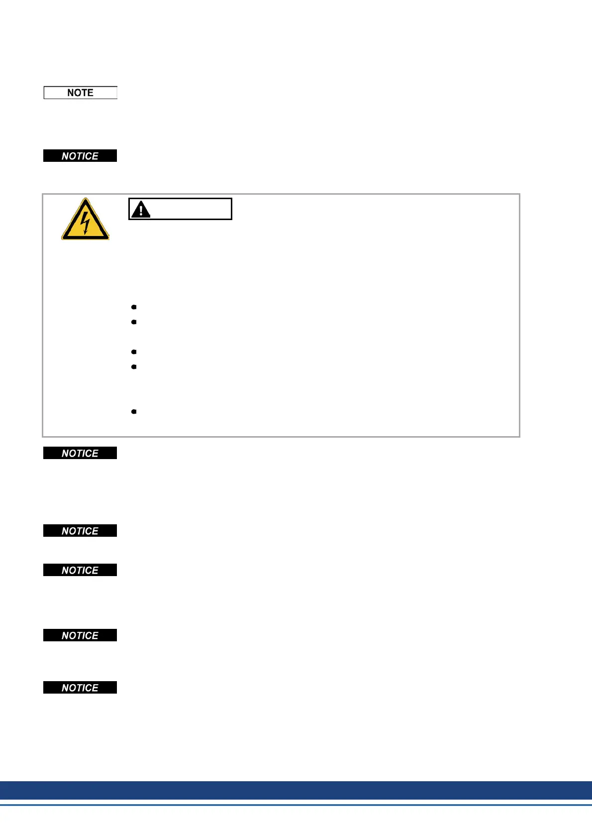
WARNING
High Voltage up to 900 V!
There is a danger of serious personal injury or death by electrical shock
or electrical arcing. Capacitors can still have dangerous voltages present
up to 10 minutes after switching off the supply power. Control and power
connections can still be live, even if the motor is not rotating.
Only install and wire the equipment when it is not live.
Make sure that the cabinet is safely disconnected (for instance, with a
lock-out and warning signs).
Never remove electrical connections to the drive while it is live.
Wait at least 10 minutes after disconnecting the drive from the main
supply power before touching potentially live sections of the equipment
(e.g. contacts) or undoing any connections.
To be sure, measure the voltage in the DC bus link and wait until it has
fallen below 50 V.
Wrong mains voltage, unsuitable motor or wrong wiring will damage the amplifier.
Check the combination of servo amplifier and motor. Compare the rated voltage and current
of the units. Implement the wiring according to the connection diagram (➜ # 192).
Make sure that the maximum permissible rated voltage at the terminals L1, L2, L3 or +DC, –
DC is not exceeded by more than 10% even in the most unfavorable circumstances (see
IEC 60204-1).
Excessively high external fusing will endanger cables and devices. The fusing of the voltage
supply must be installed by the user, best values (➜ # 57). Hints for use of Residual-current
circuit breakers (FI) see Instructions Manual.
Correct wiring is the basis for reliable functioning of the servo system. Route power and con-
trol cables separately. We recommend a distance of at least 200 mm. If a motor power cable
is used that includes cores for brake control, the brake control cores must be separately
shielded. Ground the shielding at both ends. Ground all shielding with large areas (low imped-
ance), with metalized connector housings or shield connection clamps wherever possible.
Feedback lines may not be extended, since thereby the shielding would be interrupted and
the signal processing could be disturbed. Lines between servo amplifiers and filter or
external brake resistor must be shielded. Install all power cables with an adequate cross-sec-
tion, as per IEC 60204.
The servo amplifier's status must be monitored by the PLC to acknowledge critical situ-
ations. Wire the BTB/RTO contact in series into the emergency off circuit of the installation.
The emergency off circuit must operate the supply contactor.
64 Kollmorgen | wiki-kollmorgen.eu | February 2017
 Loading...