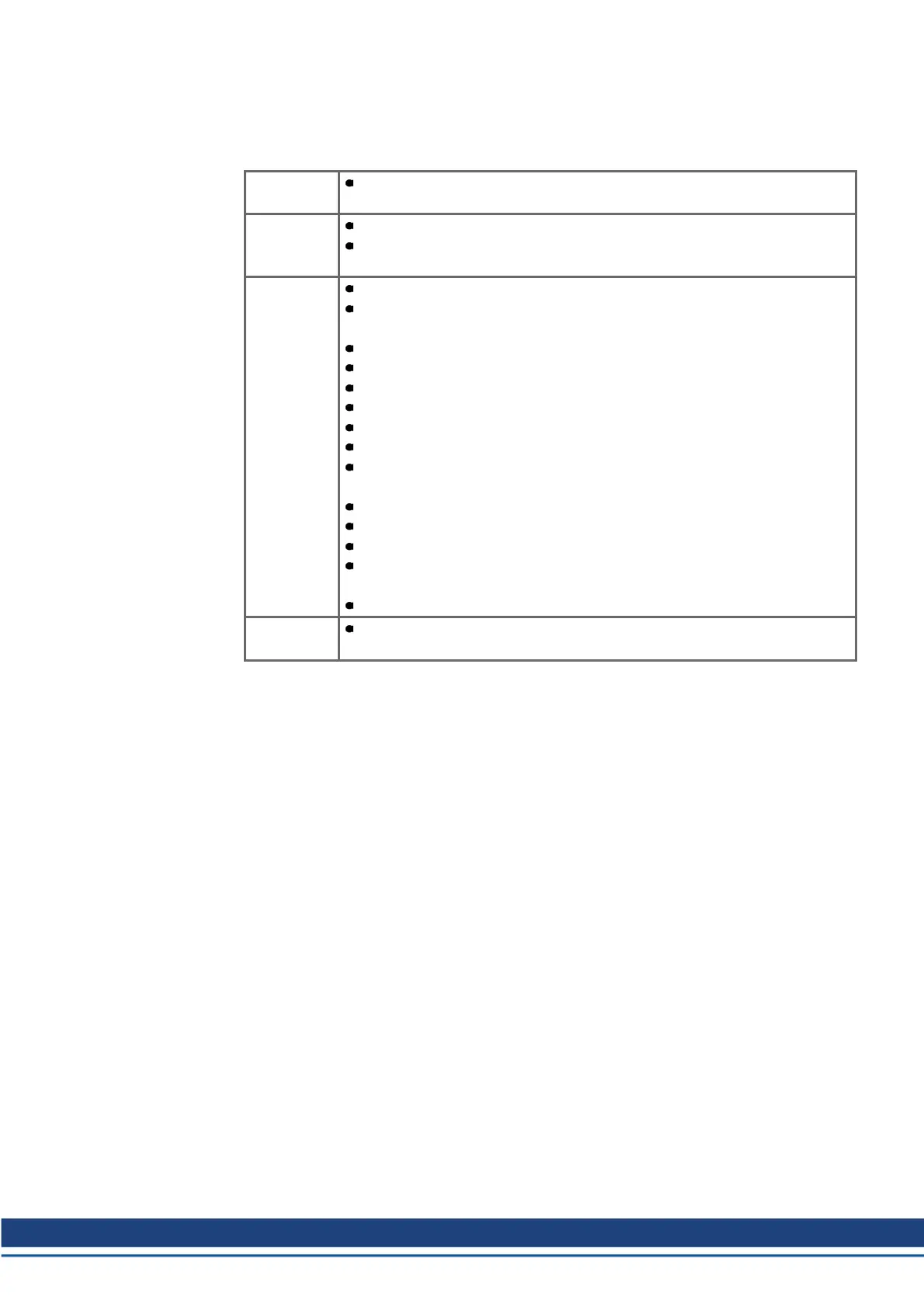
2.6.2 Guide to electrical installation
The following notes should assist you to carry out the electrical installation in a sensible
sequence, without overlooking anything important.
Cable
selection
Select cables according to EN 60204
Grounding
Shielding
EMC-compliant (EMI) shielding and grounding see Instructions Manual
Earth (ground) the mounting plate, motor housing and CNC-GND of the
controls.
Wiring Route power leads and control cables separately
Wire the BTB/RTO contact in series into the emergency off circuit of
the system.
Connect the digital control inputs to the servo amplifier
Connect up AGND (also if fieldbuses are used)
Connect the analog setpoint, if required
Connect up the feedback unit (resolver and/or encoder)
Connect the encoder emulation, if required
Connect the expansion card
Connect the motor cables, connect shielding at both ends.
S701-724: use motor chokes (3YL) for lead lengths >25m.
Connect motor-holding brake, connect shielding at both ends.
Connect the external brake resistor (with fusing) if required
Connect aux. supply (for max. permissible voltage values (➜ # 54))
Connect main power supply (for max. permissible voltage values (➜ #
54))
Connect PC.
Final check Final check of the implementation of the wiring, according to the wiring dia-
grams which have been used.
S700 Safety Guide | 2 English
Kollmorgen | wiki-kollmorgen.eu | February 2017 65
 Loading...