11. EXPLANATION OF COMPONENTS
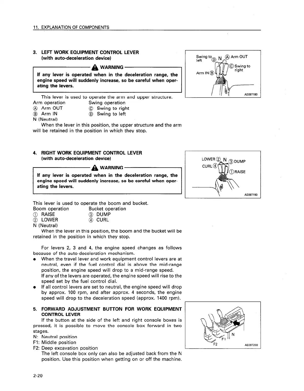
3. LEFT WORK EQUIPMENT CONTROL LEVER
(with auto-deceleration device)
a
WARNING
If any lever is operated when in the deceleration range, the
engine speed will suddenly increase, so be careful when oper-
ating the levers.
This lever is used to operate the arm and upper structure.
Arm operation Swing operation
@ Arm OUT 0 Swing to right
@ Arm IN
@ Swing to left
N (Neutral)
r
I_
When the lever in this position, the upper structure and the arm
will be retained in the position in which they stop.
Swing t
left
%
Arm IN
-
I
AE097180
4. RIGHT WORK EQUIPMENT CONTROL LEVER
1
(with auto-deceleration device)
If any lever is operated when in the deceleration range, the
be careful when oper-
AE097190
This lever is used to operate the boom and bucket.
Boom operation Bucket operation
@ RAISE
@ DUMP
@ LOWER @ CURL
N (Neutral)
When the lever in this position, the boom and the bucket will be
retained in the position in which they stop.
For levers 2, 3 and 4, the engine speed changes as follows
because of the auto-deceleration mechanism.
When the travel lever and work equipment control levers are at
neutral, even if the fuel control dial is above the mid-range
position, the engine speed will drop to a mid-range speed.
If any of the levers are operated, the engine speed will rise to the
speed set by the fuel control dial.
If all control levers are set to neutral, the engine speed will drop
by approx. 100 rpm, and after approx. 4 seconds, the engine
speed will drop to the deceleration speed (approx. 1400 rpm).
FORWARD ADJUSTMENT BUT-TON FOR WORK EQUIPMENT
CONTROL LEVER
If the button at the side of the left and right console boxes is
pressed, it is possible to move the console box forward in two
stages.
N: Neutral position
Fl: Middle position
F2: Deep excavation position
The left console box only can also be adjusted back from the N
position. Use this position when getting on or off the machine.
F2
AE097200
2-20