Technicalspecications
Note
Allterminalpinnumberinggoesfromleft(no.1)toright.
3.12.3RS-422AandBsignaldenition
Accordingtothefollowingstandardthesignalstatedenitionsare:
•IEC61162-1.Theidle,marking,logical1,OFForstopbitstatesaredenedbya
negativevoltageonlineAwithrespecttolineB.Theactive,spacing,logical0,ON
orstartbitstatesaredenedbyapositivevoltageonlineAwithrespecttolineB.
ItshouldbenotedthattheaboveAwithrespecttoBlevelsareinvertedfromthe
voltageinput/outputrequirementsofstandardUARTsandthatmanylinedrivers
andreceiversprovidealogicinversion.
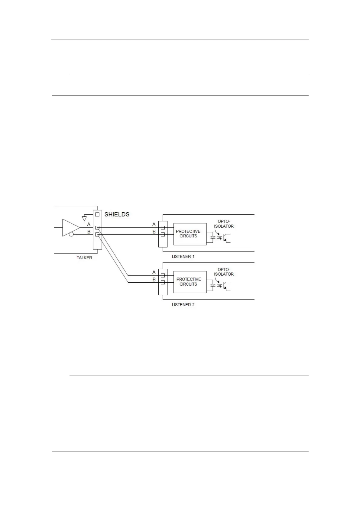
Figure3Principledrawingfortalkerandlistenercircuits
TheRS–422serialportsontheProcessingUnithavegalvanicisolationonbothtalker
(transmit-TX)andlistener(receive-RX).InterfacecircuitsarefedbyaDC/DC
converterwithgalvanicisolation(transformer)andsignalisolationisprovidedby
optocouplerstypeHPCL06.Transmitter/receiverdatacircuitsareoftypeLTC491.The
transmitpartmayfeedupto32listenersiftheminimumDCloadisabove60Ohm.The
receiver-RXterminationintheProcessingUnit(100R)isswitchedonoffbyFW/SW.
Note
Withreferencetothetableshowingthepinlayoutfortheserialportsontherearpanel
screwterminals,notethattheseparate“GND”pinforeachportisisolatedfromthe
chassisandshallactasacommonsignalintendedtobeconnectedbetweenthetalker
(-TX)andthelistenerside(RX)ofotherequipment,forexamplethecorresponding
isolated“GND”pinorcommonpin.Thepurposeofthecommonsignalistoincrease
thereliabilityofthehardwaretransmission.Itmustnotbeconnectedtothechassisor
thecablescreen.Thisappliestobothsidesofaconnection.Thecablescreenshallbe
connectedtotheequipmentchassisononesideonly,preferablytalkerside,-TX.
G210-14/3.0
27