Installation
4.6Electricalinstallation
Theelectricalinstallationconsistsof:
•ConnectingacablebetweentheGNSSantennaandtheProcessingUnit.
•ConnectingacablebetweentheIALAantennaandtheProcessingUnit.
•ConnectingcableswithoutputdatabetweentheProcessingUnitandexternal
equipment.
•ConnectingcableswithDGNSScorrectionstotheProcessingUnit(optional).
•Connectingmonitor,keyboardandmouse.
•SupplyingpowertotheProcessingUnit.
Caution
AttachtheantennacabletotheGNSSantennaonthemountingrodbefore
attachingtheantennacablestotheProcessingUnit.Iftheantennacable
isattachedtotheProcessingUnit,donotattachtheantennacablestothe
GNSSantennawiththeProcessingUnitpoweredon.Iftheantennacable
isshort-circuitedwithpoweron,theGNSSreceiverswithintheProcessing
Unitwillbedamaged.
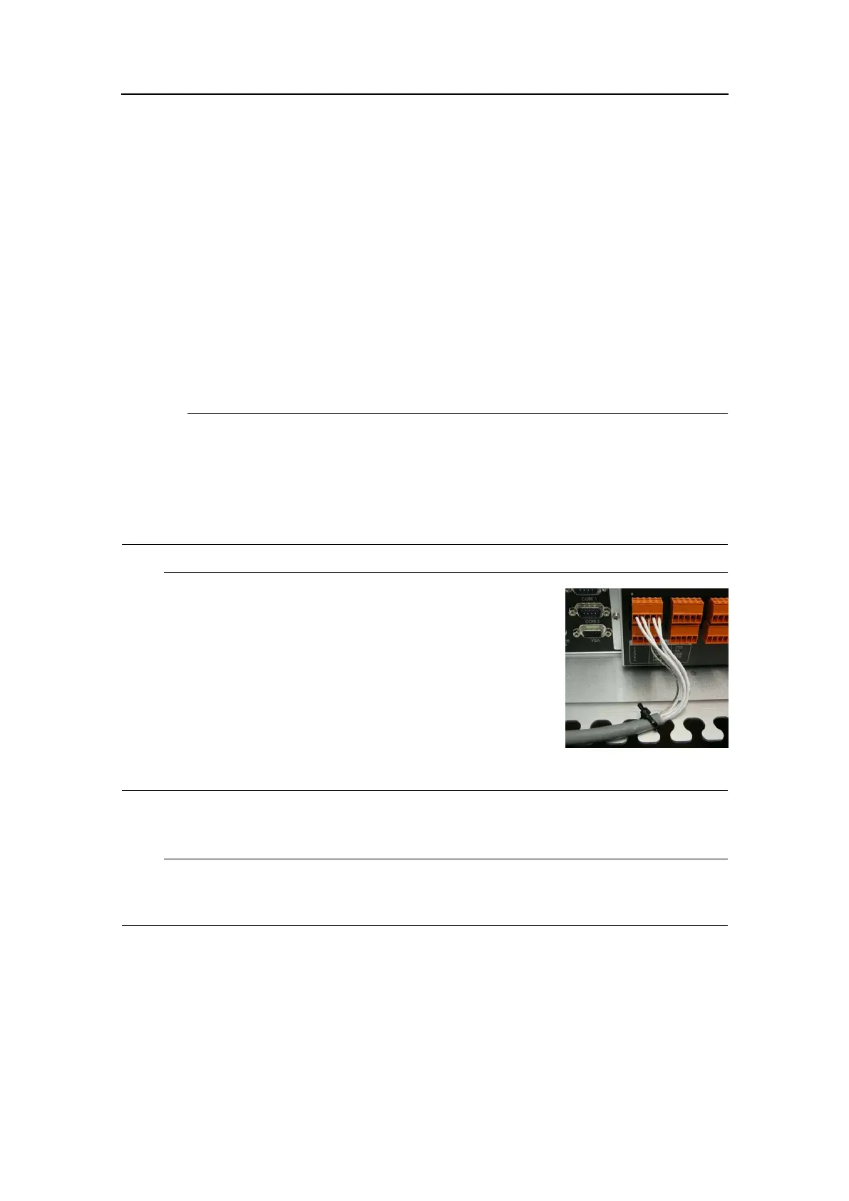
Note
Donotplacethecableinbetweenthetonguesattherear
oftheunitbutfastenthecablewithstripsasillustrated.
Howtocarryouttheelectricalinstallation
Note
Theantennacablesmustbeasstraightaspossible.Donotcrushorcrimpthecablewith
tie-downsasthiswillaffecttheelectricalpropertiesofthecables.
1ConnecttheGNSSantennacabletotheconnectormarkedGNSS1attherearofthe
ProcessingUnit.
2ConnecttheIALAbeaconcabletotheconnectormarkedIALAattherearofthe
ProcessingUnit.
3ConnectthecablesforoutputdatafromtheProcessingUnittoexternalequipment
totheportsCom1,Com2ortheterminalsCom9throughCom14,analogoutput
signalsortheEthernetconnections.
G210-14/3.0
45