48
2.2 Component names and functions
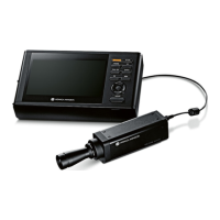
2.2.6 Detector Interface Unit
The component names and functions of the Detector Interface Unit are as follows.
(1) Base cover
(2) LED
(4) LAN port
(10) AC adapter
(9) Power cable
(5) Unit fixed plate
(8) Power cable connector
(6) Power cable connector socket (7) Location for connecting
the grounding cable
(3) Cable outlet
Number Name Functions
(1) Base cover Protects the internal parts.
(2) LED Indicates the status of the Detector Interface Unit.
(3) Cable outlet Outlet for I/F Cable.
(4) LAN port Connects to the Ethernet cable.
(5) Unit xed plate Used to attach this device to a wall stand or table, etc.
(6) Power cable connector socket This is the socket of the Power cable connector.
(7)
Location for connecting the grounding
cable
Used to connect the grounding cable. Not usually used.
(8) Power cable connector
Plug into the power cable socket of Detector Interface Unit.(9) Power cable
(10) AC adapter
 Loading...