3.2 Operation of DR Detector
72
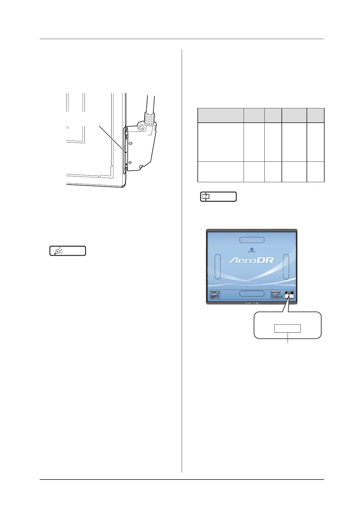
Wired connection
• When performing exposure with a wired connec-
tion, fasten the wired cable horizontally to the
wired connection connector of the DR Detector. If
connected at an angle, transverse (noise) some-
times gets into acquired images after exposure.
Connect it such that
there is no space.
Wireless communications environment
• With a wireless environment, it is possible that
errors such as no wireless connection, wireless
communication terminates, and lengthened expo-
sure cycle time might occur.
HINT
•••••••••••••••••••••••••••••••••••••
• Problems with a wireless communications environ-
ment can occur in the following conditions:
– Installed location of the access point is not good.
– When inserted in the wall stand, table, or stretcher,
the opening in the wall stand or table is too small
and there is no passage for the radio waves.
– The radio waves are not emitted due to metal parts
close to the antenna, which changes the antenna
characteristics.
– For exposures where the body touches the DR
Detector directly, the radio waves may not be emit-
ted if the body completely covers both antennas or
either of the antennas.
– Other devices use the same radio band, and cause
interference.
– When the 2.4 GHz band is used, using high
frequency therapy equipment will cause interference.
– When the DFS band is used, the access point
changes channels if weather radar or air control
radar is detected. This may cause communication
to be temporarily disconnected.
•••••••••••••••••••••••••••••••••••••••••••••••••••••
Exposure switch
• If the exposure switch remains held down, it may
result in an afterimage becoming visible. Once
exposure is nished, release the exposure switch
immediately.
Grid
• Use the following grid when exposing.
DR Detector
Grid
density
Grid
ratio
Convergence
distance
Angle
error
AeroDR 1417HQ,
AeroDR 1417S,
AeroDR 1717HQ,
AeroDR 1012HQ,
AeroDR 2 1417HQ,
AeroDR 2 1417S
34 lp/cm
40 lp/cm
Variety Variety
5.0° or
less
AeroDR 3 1417HD,
AeroDR 3 1717HD,
AeroDR 3 1012HQ
34 lp/cm
40 lp/cm
60 lp/cm
Variety Variety
5.0° or
less
IMPORTANT
•••••••••••••••••••••••••••••••••••••
• For an AeroDR 1417S without the "1417S" identica-
tion, use a grid with a grid density of 34 lp/cm and an
angle error of 0.5° or less.
1417S
AeroDR P-12
()
Identication
• A capped grid is recommended when laying the grid
over the DR Detector on the table top or for exposure
with the X-ray device.
• Do not use a grid of which the antenna is covered with
metal, as the quality of wireless communication may
be signicantly reduced.
•••••••••••••••••••••••••••••••••••••••••••••••••••••
 Loading...