KT690 Family
KTD-00738-C Public User Manual Date: 2008-09-16 Page 33 of 91
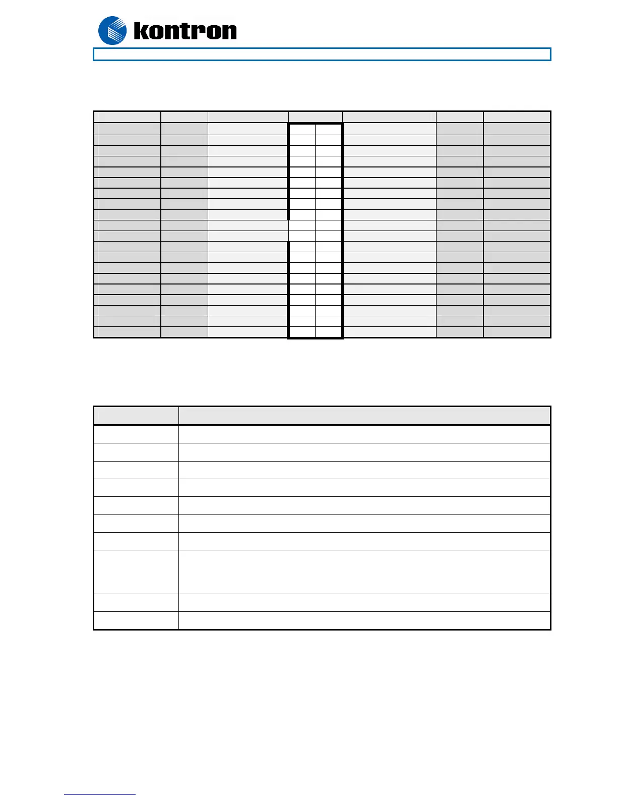
4.4.3 LVDS Flat Panel Connector (LVDS)
Note Type Signal Pin Signal Type Note
Max. 0.5A PWR +12V 1 2 +12V PWR Max. 0.5A
Max. 0.5A PWR +12V 3 4 +12V PWR Max. 0.5A
Max. 0.5A PWR +12V 5 6 GND PWR Max. 0.5A
Max. 0.5A PWR +5V 7 8 GND PWR Max. 0.5A
Max. 0.5A PWR LCDVCC 9 10 LCDVCC PWR Max. 0.5A
2K2, 3.3V OT DDC CLK 11 12 DDC DATA OT 2K2, 3.3V
3.3V level OT BKLTCTL 13 14 VDD ENABLE OT 3.3V level
3.3V level OT BKLTEN# 15 16 GND PWR Max. 0.5A
LVDS LVDS A0- 17 18 LVDS A0+ LVDS
LVDS LVDS A1- 19 20 LVDS A1+ LVDS
LVDS LVDS A2- 21 22 LVDS A2+ LVDS
LVDS LVDS ACLK- 23 24 LVDS ACLK+ LVDS
LVDS LVDS A3- 25 26 LVDS A3+ LVDS
Max. 0.5A PWR GND 27 28 GND PWR Max. 0.5A
LVDS LVDS B0- 29 30 LVDS B0+ LVDS
LVDS LVDS B1- 31 32 LVDS B1+ LVDS
LVDS LVDS B2- 33 34 LVDS B2+ LVDS
LVDS LVDS BCLK- 35 36 LVDS BCLK+ LVDS
LVDS LVDS B3- 37 38 LVDS B3+ LVDS
Max. 0.5A PWR GND 39 40 GND PWR Max. 0.5A
Note 1: The KT690 board support dual channel, 24bit OpenLDI/ SPWG panels on the LVDS interface
Signal Description – LVDS Flat Panel Connector:
Signal Description
LVDS A0..A3 LVDS A Channel data
LVDS ACLK LVDS A Channel clock
LVDS B0..B3 LVDS B Channel data
LVDS BCLK LVDS B Channel clock
BKLTCTL Backlight control (1), PWM signal to implement voltage in the range 0-3.3V
BKLTEN# Backlight Enable signal (active low) (2)
VDD ENABLE Output Display Enable.
LCDVCC VCC supply to the flat panel. This supply includes power-on/off sequencing.
The flat panel supply may be either 5V DC or 3.3V DC depending on the CMOS
configuration. Maximum load is 1A at both voltages.
DDC CLK DDC Channel Clock
DDC DATA DDC Channel Data
Note 1) Windows API will be available to operate the BKLTCTL signal. Some Inverters has a limited voltage
range 0- 2.5V for this signal: If voltage is > 2.5V the Inverter might latch up. Some Inverters
generates noise to the BKLTCTL signal resulting in making the lvds transmision fail (corrupted
picture on the display). By adding 1K Ohm resistor in series with this signal and mounted in the
Inverter end of the cable kit the noise is limited and picture is stabil.
Note 2) If the Backlight Enable is required to be active high then make the BIOS Chipset setting: Backlight
Signal Inversion = Enabled.