KT690 Family
KTD-00738-C Public User Manual Date: 2008-09-16 Page 50 of 91
4.14 Audio Connector
The onboard Audio circuit implements 7.1+2 Channel High Definition Audio, featuring ten 24-bit stereo DACs
and two 20-bit stereo ADCs.
Thew Audio signals are made available on the Frontpanel stacked connector (Line in / Line out / MIC) and
the onboard AUDIO_HEAD and CDROM Audioinput connectors.
4.14.1 Audio Line-in, Line-out and Microphone
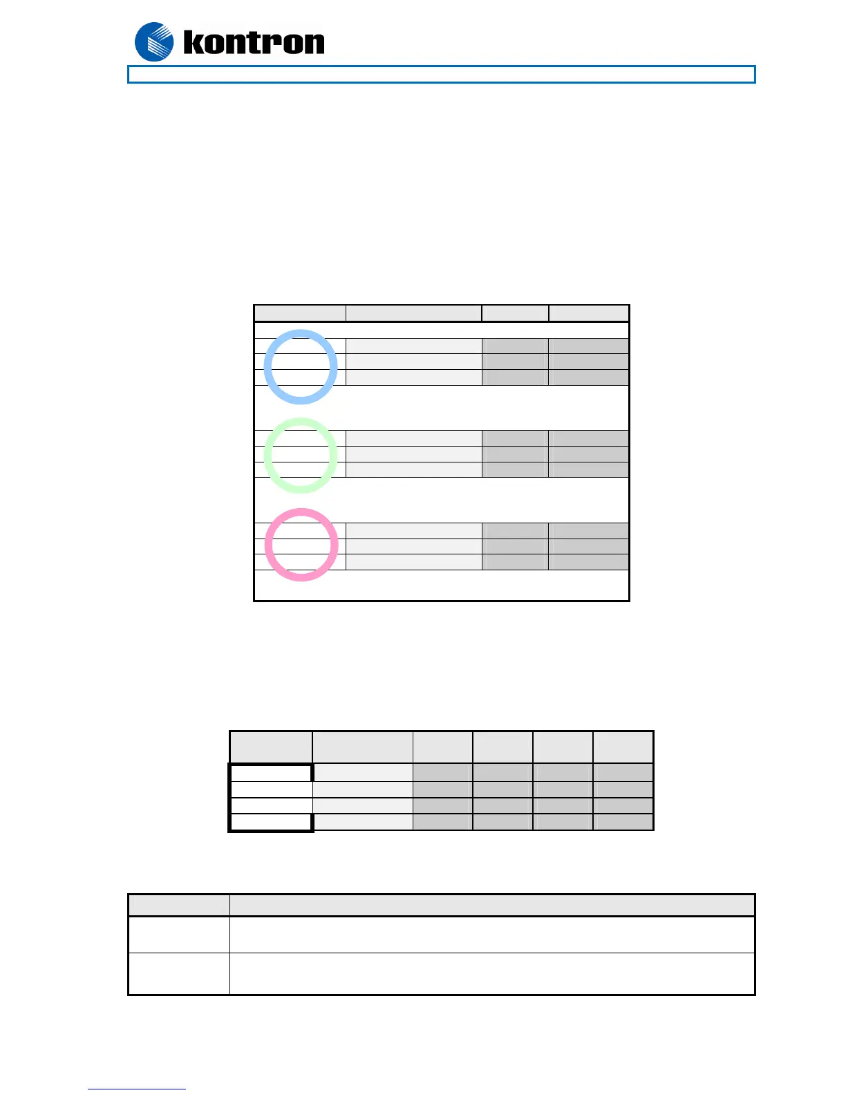
Audio Line-in, Line-out and Microphone are available in the stacked audio jack connector.
IN Signal Type Note
TIP LINE1-IN-L IA 1
RING LINE1-IN-R IA 1
SLEEVE GND PWR
TIP FRONT-OUT-L OA
RING FRONT-OUT-R OA
SLEEVE GND PWR
TIP MIC1-L IA 1
RING MIC1-R IA 1
SLEEVE GND PWR
Note 1: Signals are shorted to GND internally in the connector, when jack-plug not inserted.
4.14.2 CD-ROM Audio input (CDROM)
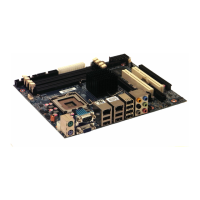
CD-ROM audio input may be connected to this connector. It may also be used as a secondary line-in signal.
PIN Signal Type Ioh/Iol Pull
U/D
Note
1 CD_Left IA - - 1
2 CD_GND IA - -
3 CD_GND IA - -
4 CD_Right IA - - 1
Note 1: The definition of which pins are use for the Left and Right channels is not a worldwide accepted
standard. Some CDROM cable kits expect reverse pin order.
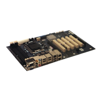
Signal Description
CD_Left
CD_Right
Left and right CD audio input lines or secondary Line-in.
CD_GND Analogue GND for Left and Right CD.
(This analogue GND is not shorted to the general digital GND on the board).