KIT-400 – Defining KIT-400 4K Auto-Switcher/Scaler Kit
Set the device behavior (see Setting KIT-400T DIP-switches
on page 13).
SERVICE Mini USB Connector
Connect to a PC to perform a firmware upgrade.
Lights blue when a link is established with the receiver.
Follow powering instructions in (see Connecting KIT-400 on page 9).
Failure to use PoC and power connector correctly may destroy the devices!
PoC (Power over Cable) Switch
Set the PoC switch to ON on both KIT-400T and KIT-400R.
Connect to the supplied power adapter, unless the power
adapter is connected to KIT-400R.
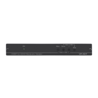
Defining KIT-400R
Figure 2: KIT-400R 4K HDBT/HDMI Receiver/Scaler
Connect to a USB stick to perform firmware upgrades.
Press to select the input (HDBT or HDMI).
By default, the SELECT button is locked. You can unlock
it via the ADVANCED menu in the OSD (see Locking
KIT-400R Input Buttons on page 18).
Lights blue when the HDBT input is selected.
Lights blue when the HDMI input is selected.
Press to enter/exit the on-screen display (OSD) menu. Press
together with the – button to reset to 1080p.
In OSD, press to choose the highlighted menu item. Press
together with the FREEZE/+ button to reset to XGA.
In OSD, press to move back through menus or decrement
parameter values.
In OSD, press to move forward through menus or increment
parameter values. When not in OSD, press to freeze the
display.
Lights blue when a link is established with the transmitter.
Lights green when device is powered.
Connect to an HDMI source.
Connect to an HDMI acceptor.
AUDIO 5-pin Terminal
Block Connector
Connect to a balanced stereo audio acceptor.
REMOTE Contact-Closure 4-pin
Terminal Block Connector
Connect to contact closure switches, an occupancy sensor
and/or toggle switches (contact between the desired pin and
GND pin), to turn the display on or off. (See Using Remote
Control Switches on page 12).