VS-211XS, VS-411XS – Defining VS-211XS and VS-411XS
VS-211XS / VS-411XS Rear Panel
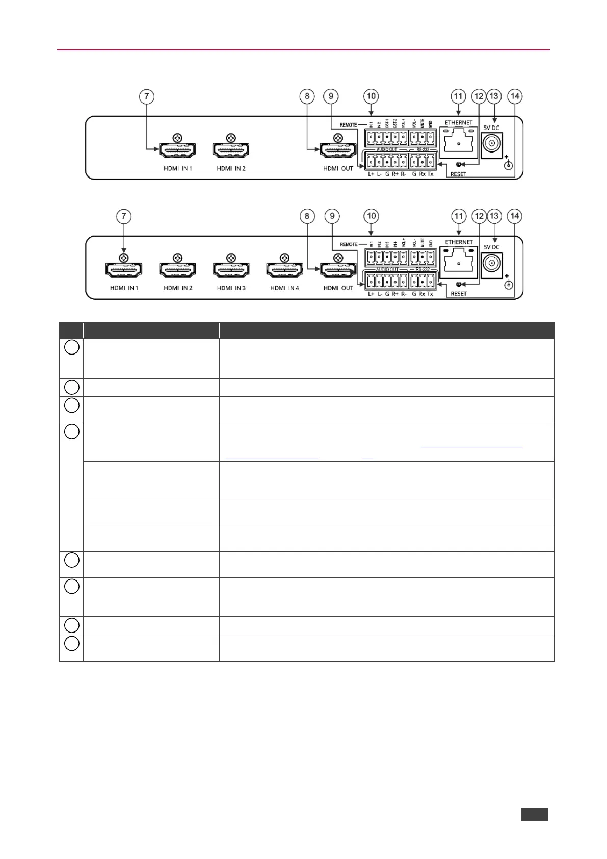
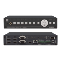
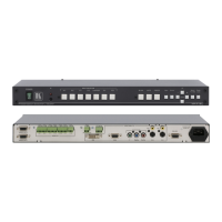
Figure 3: VS-211XS 2x1 4K Auto Switcher Rear Panel
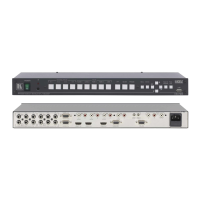
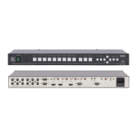
Figure 4: VS-411XS 4x1 4K Auto Switcher Rear Panel
Connect to an HDMI source:
VS-211XS: HDMI IN 1 and HDMI IN 2.
VS-411XS: HDMI IN 1 to HDMI IN 4.
Connect to an HDMI acceptor.
AUDIO OUT 5-pin Terminal
Block Connector
Connect to a balanced stereo audio acceptor.
REMOTE Terminal block
Connector:
Connect to contact closure switches by momentary contact between
the desired pin and common GND pin (see Using Contact Closure
Remote Control Pins on page 16).
For VS-211XS:
IN 1, IN 2/ CST-1, CST-2
Select input 1 or input 2 (IN 1 or IN 2), or alternatively activate custom
triggers (including CST-1 and CST-2 to GND) set up in Maestro.
(Configured via the embedded web pages).
For VS-411XS:
IN 1, IN 2, IN 3, IN 4
Select input 1 to input 4 (IN 1 to IN 4), or alternatively activate custom
triggers set up in Maestro. (Configured via the embedded web pages).
Set the volume up or down (VOL+/-) and mute the audio output
(MUTE).
Connect to a PC via a LAN to control the device.
Press briefly to restart the device.
Press and hold (5 seconds) to fully reset the device parameters to their
default values, including ETH parameters.
Connect to the power supply and to the mains electricity.
RS-232 3-pin Terminal
Block Connector
Connect to a PC or a remote controller to control the device.