4 Description of the Pump (Set)
19 of 82
Amarex
2573.820/02-EN
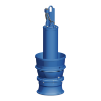
4.7 Configuration and function
1 Shaft 2 Bearing bracket
3 Discharge cover 4 Discharge nozzle
5 Suction cover 6 Suction nozzle
7 Impeller 8 Shaft seal
9 Bearing, pump end 10 Bearing, motor end
Design The pump is designed with an axial fluid inlet and a radial outlet. The hydraulic
system sits on the extended motor shaft. The shaft runs in common bearings.
Function The fluid enters the pump axially via the suction nozzle (6) and is accelerated
outward in a cylindrical flow by the rotating impeller (7). In the flow passage of the
pump casing the kinetic energy of the fluid is converted into pressure energy. The
fluid is pumped to the discharge nozzle (4), where it leaves the pump. At the rear
side of the impeller, the shaft (1) enters the hydraulic system via the discharge cover
(3). The shaft passage through the cover is sealed to atmosphere with a shaft seal (8).
The shaft runs in rolling element bearings (9 and 10), which are supported by a
bearing bracket (2) joined to the pump casing and/or discharge cover.
Sealing The pump is sealed by two bi-directional mechanical seals in tandem arrangement.
A lubricant reservoir in-between the seals ensures cooling and lubrication of the
mechanical seals.
4.8 Scope of supply
Depending on the model, the following items are included in the scope of supply:
Stationary wet-installed model (installation type S)
▪ Pump set complete with power cables
▪ Claw with sealing elements and fasteners
▪ Mounting bracket with fasteners
▪ Duckfoot bend with mounting elements
▪ Guiding equipment
5)
5
The guide rails are not included in the scope of supply.