5 Installation at Site
26 of 82
Amarex
2573.820/02-EN
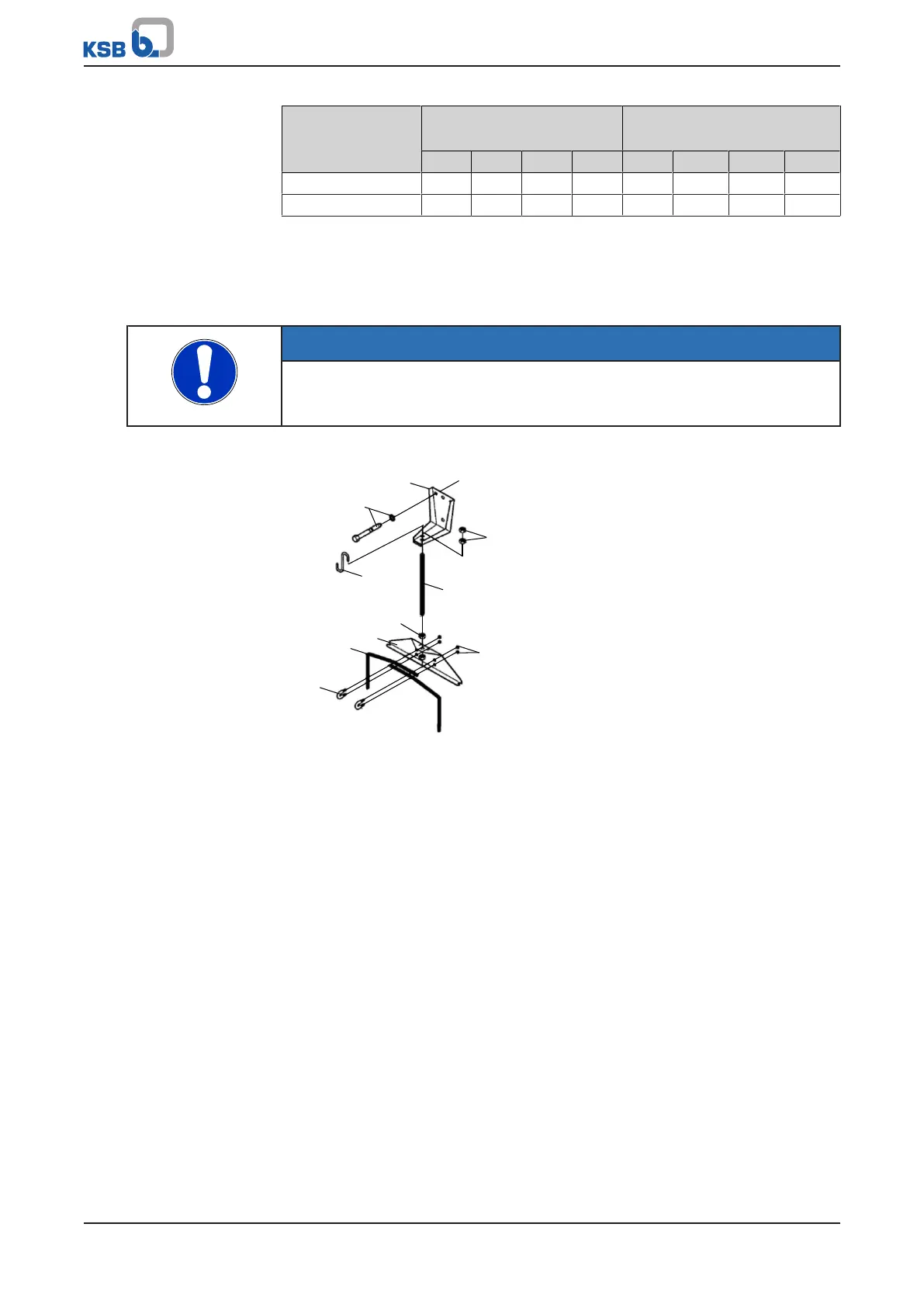
Nominal flange
diameter
Forces
[N]
Moments
[Nm]
F
y
F
z
F
x
∑F M
y
M
z
M
x
∑M
100 2700 3350 3000 5250 1250 1450 1750 2600
150 4050 5000 4500 7850 1750 2050 2500 3650
5.3.1.3 Fitting the guide wire arrangement
The pump set is guided into the sump or tank along two parallel, tightly stretched
guide wires made of stainless steel. It attaches itself automatically to the duckfoot
bend which has been fitted to the floor.
NOTE
Should site conditions/piping layout, etc. require the wire to run off the vertical, do
not exceed a maximum angle of 5° to ensure reliable fitting and guiding of the
pump set.
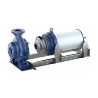
Fitting the mounting bracket
894
90-3.37
59-18
904
920.36
920.37
920.36
572
59-24.01
571
Fig.7: Fitting the mounting bracket
1. Fasten mounting bracket 894 to the edge of the sump opening with anchor
bolts 90-3.37 and tighten the anchor bolts to a tightening torque of 10Nm.
2. Insert clamping pieces 571 through the holes of suspension bracket 572 and
fasten with nuts 920.37.
3. Fasten fully threaded stud 904 with the pre-assembled clamping arrangement to
the mounting bracket with nut 920.36.
Tighten nut 920.36 allowing sufficient play for subsequently tensioning the
guide wire.