5 Installation at Site
27 of 82
Amarex
2573.820/02-EN
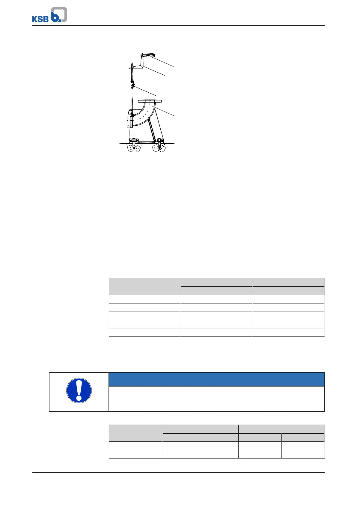
Inserting the guide wire
Fig.8: Inserting the guide wire
1. Lift clamping piece 571 and insert one end of the guide wire.
2. Run wire 59-24.01 around duckfoot bend 72-1 and back again to suspension
bracket 572 and insert it into clamping piece 571.
3. Manually tension wire 59-24.01 and secure it by means of hexagon nuts 920.37.
4. Pull the wire taut by tightening hexagon nut(s) 920.36 on the upper side of the
mounting bracket.
Refer to the "Guide wire tension" table.
5. Secure the nuts with a second hexagon nut.
6. The loose wire ends at guide wire suspension bracket 572 can either be twisted
into a ring or the end can be cut off.
After length adjustment, tape the ends to avoid fraying.
7. Attach hook 59-18 to mounting bracket 894 for attaching the lifting chain/
lifting rope at a later stage.
Table13: Guide wire tension
Size Tightening torque Guide wire tension
M
A
[Nm] P [N]
50 - ... 9 6000
65 - ... 9 6000
80 - ... 14 6000
100 - ... 14 6000
150 - ... 14 6000
5.3.1.4 Fitting the guide rail arrangement
The pump set is guided into the sump or tank along one or two vertical guide rails. It
attaches itself automatically to the duckfoot bend which has been fitted to the floor.
NOTE
The guide rails are not included in the scope of supply.
Select guide rail materials which are suitable for the fluid handled or as specified by
the operator.
Table14: Guide rail dimensions
Hydraulic system
size
Outside diameter Wall thickness [mm]
8)
[mm] Minimum Maximum
DN 50 33,7 2 5
DN 65 33,7 2 5