5 Installation at Site
28 of 82
Amarex
2573.820/02-EN
Hydraulic system
size
Outside diameter Wall thickness [mm]
8)
[mm] Minimum Maximum
DN 80 60,3 2 5
DN 100 60,3 2 5
DN 150
9)
60,3 2 5
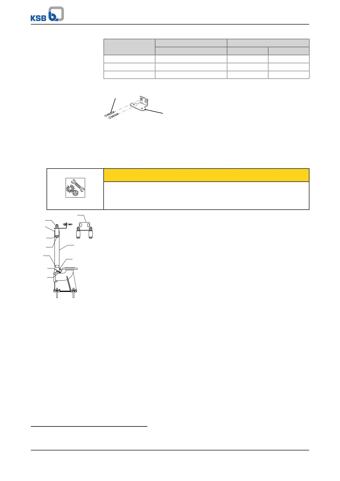
Fitting the mounting bracket
Fig.9: Fitting the mounting bracket
1. Fasten mounting bracket 894 to the edge of the sump opening with steel
anchor bolts 90-3.37 and tighten the anchor bolts to a tightening torque of
10Nm.
Observe the hole pattern for the anchor bolts. (See outline drawing.)
Fitting the guide rails (twin guide rail arrangement)
CAUTION
Improper installation of the guide rails
Damage to the guide rail arrangement!
▷ Always adjust the guide rails so that they are in a perfectly vertical position.
920.01
81.51
894
710
914.02
550.01
914.01
82.5
550.02
920.02
Fig.10: Fitting two guide
rails
1. Position adapter 82.5 on duckfoot bend 72.1 and fasten it with screws 914.02,
discs 550.02 and nuts 920.02.
2. Place rails 710 onto the conical bosses of adapter 82.5 and position them
vertically.
3. Mark the length of rails 710 (up to the lower edge of the mounting bracket),
taking into account the adjusting range of the slotted holes in mounting
bracket 894.
4. Shorten rails 710 with a 90° cut to the pipe axis. Debur the rails inside and
outside.
5. Insert mounting bracket 894 with clamping sleeves 81.51 into guide rails 710
until the mounting bracket rests on the rail ends.
6. Tighten nuts 920.01.
This expands the clamping sleeves so that they clamp the rails at the inside rail
diameter.
7. Secure nut 920.01 with a second nut.
8
To DIN2440/2442/2462 or equivalent standards
9
Only with twin guide rail arrangement
 Loading...