5 Installation at Site
31 of 82
Amarex
2573.820/02-EN
5.3.1.7 Installing the pump set
NOTE
Make sure the pump set with the pre-assembled claw can easily be slipped over the
mounting bracket, threaded onto the guide rails and lowered down. If required,
alter the position of the crane during installation.
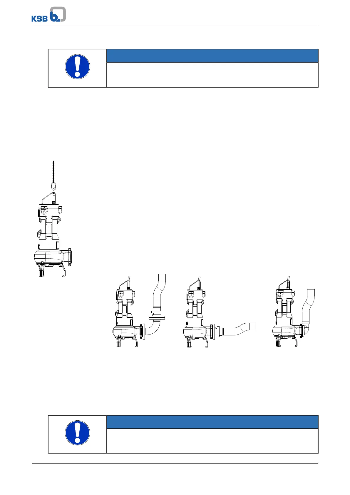
1. Guide the pump set over the suspension bracket/ mounting bracket and slowly
lower it down along the guide wires/ guide rails.
The pump set attaches itself to duckfoot bend 72-1.
2. Attach the lifting chain/rope to hook 59-18 at the mounting bracket.
5.3.2 Transportable wet-installed model
Before installing the pump set, fit the three pump feet and foot plate if applicable.
Fitting the pump feet
Fig.15: Attaching the lifting
chain/ lifting rope
1. Undo screws 914.03.
2. Push pump feet 182 into the openings in the suction cover.
3. Tighten screws 914.03 again to the indicated tightening torque.
(ðSection7.6,Page55)
Fitting the foot plate
1. Fit the foot plate to the three pump feet with bolts/screws, discs and nuts.
Observe the tightening torques. (ðSection7.6,Page55)
Attaching the lifting chain / lifting rope
1. Attach the lifting chain/ lifting rope to the shackle on the discharge nozzle side
of the pump set (see illustration and "Types of attachment" table).
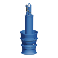
Connecting the piping
The DIN connection can be connected to rigid or flexible pipes.
Fig.16: Connection options
5.4 Electrical system
5.4.1 Information for planning the control system
For the electrical connection of the pump set observe the "Wiring diagrams" section.
(ðSection9.3,Page69)
The pump set is supplied with power cables; it is wired for DOL starting.
NOTE
When laying a cable between the control system and the pump set's connection
point, verify that the number of cores is sufficient for the sensors. A minimum cross-
section of 1mm² is required.