Submersible motor pumps (100 mm)
3
2.3 Typical installation at site
Use lifting device of capability of carrying the weight of pump
unit as well as the weight of pipe filled with water for installation.
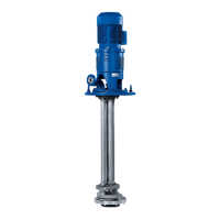
2.3.1 Vertical installation
Before installing the unit in narrow deep wells, the well should be
tested for trueness of size over its entire length (e.g. by running
a dummy cylinder of diameter 98 mm and length about 2 m inside
the well). A slight inclination of the well is immaterial, whereas
any twists or bends can make installation difficult.
Installation depth should be selected such that the motor would
never run dry even when the water level is at its lowest mark
(i.e. draw down of bore well capacity).
The minimum water level should be 0.5 m above the top of the
non-return valve.
The pump should always be installed with the suction strainer
above the slotted casing pipe. The effect is that the pump draws
in the water free from loose sand.
1. Discharge valve
2. Supporting clamp
3. Raiser pipe
4. Submersible motor-Pump set
5. Power supply cable
6. Starter
7. Slotted Casing pipe
(Length up to rock level)
8. Pressure Gauge
D = Well diameter
T
B
= Well depth
H
e
= Installation depth
H
h
= Stationary water level
H
t
= Operation water level
H
geo
= Geostatic head
Ht - Hh = Drawdown
Notes for installation :
The motor pump unit must be immersed minimum 0.5 m more
below the lowest operation water level H
t
.
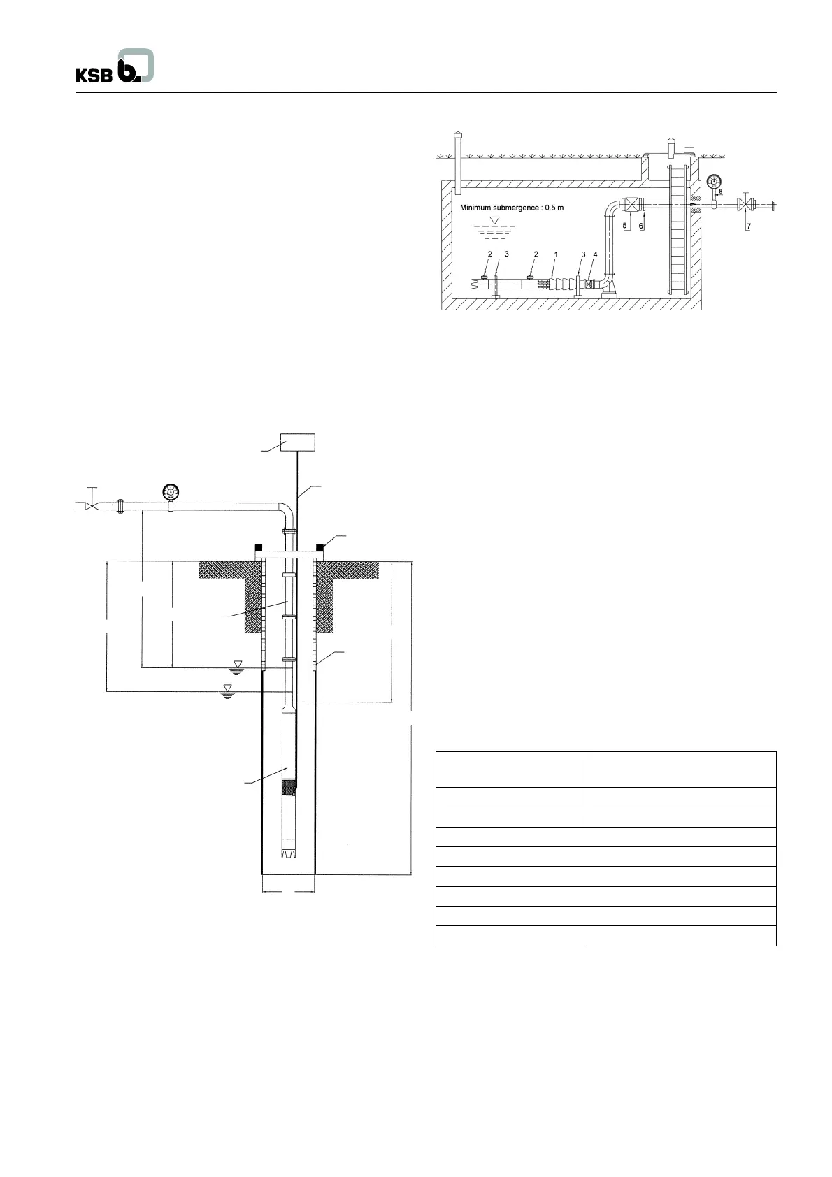
2.3.2 Horizontal Installation (e.g. in tank or pit)
Note : Generally the horizontal installation of submersible pump
unit is equipped with two storage tanks to increase the water
capacity.
1. Referring to the above figure (Fig. 4) for horizontal installation
only two supports are needed. One is placed at the extreme
end of the NRV while other is placed at the center of motor.
2. Install adapter pipe to the pump with 2 Water reservior and
the motor with proper fittings.
3. Ensure that the cast RCC foundation is incorporated with
the recommended foundation bolts of proper height.
4. To make up the correct center height of aligned pump - motor,
provide sufficient metallic packing in the RCC foundation
itself. To attain precise alignment, minor shims up to 2 mm
thick made of M.S. sheet may be used below the pump or
motor stand.
5. Such installed pump shall be either perfectly horizontal or
maximum of 5 degree inclination with motor down and pump
lifted up from the ground. Precise tightening of foundation
bolts has to be done at the final stage.
6. Surface of the motor should be cleaned periodically for
effective cooling.
1. Submersible pump unit
2. Water reservior for Motor
3. Support
4. Expansion joint
5. Non-return valve
6. Flange adapter
7. Discharge valve
8. Pressure gauge
It is important to ensure that pump does not sit on the base of the
well and there is no risk of sand or sludge deposition around the
motor. This would disrupt heat dissipation from the motor.
2.3.3 Plastic / Flexible Rubber riser piping instead
of normal GI riser piping
Consult the HDPE / rubber pipe suppliers for the capability of
pipes for withstanding the pressure. If the pump is to be fitted
with HDPE raising piping, it is to be firmly tied up with stainless
steel wire ropes of dia. 2-3 mm to the eyelets on the non return
Fig. no. 3
1
8
6
5
2
3
7
H t
H geo
H h
H e
T
8
4
D
Pump type Max. no. of stages allowed
for horizontal installation
CORA 1C & CORA 2C 30
CORA 4C 23
CORA 7C 19
CORA 12C 8
CORA 18C 8
CORA 2AH 17
CORA 3AH 12
CORA 3A 15
Fig. no. 4