Submersible motor pumps (100 mm)
4
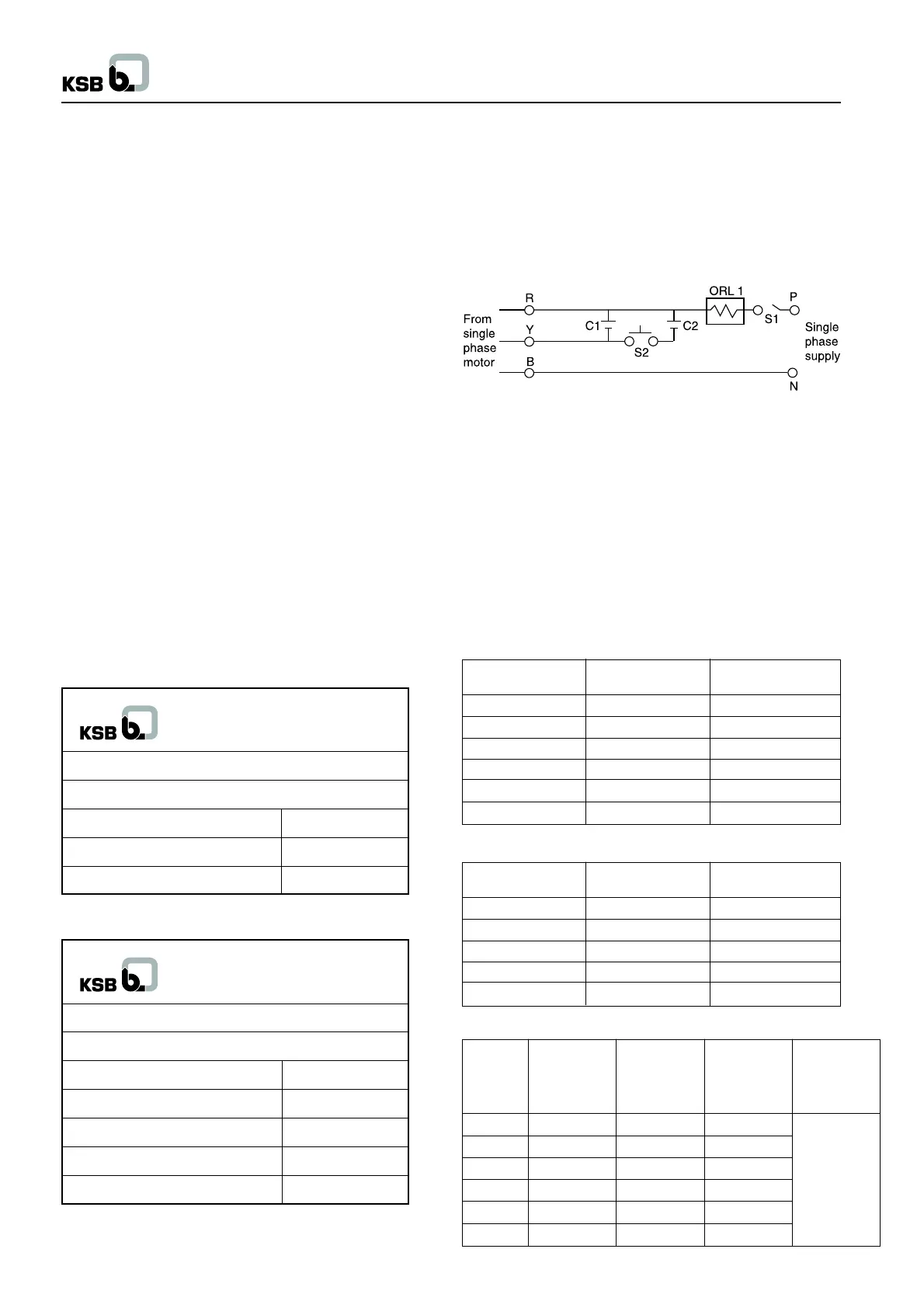
R : Red color wire C2 : Starting capacitor
B : Blue color wire C1 : Running capacitor
Y : Yellow color wire ORL 1 : Overload relay
S1 : On-off main switch P : Phase
S2 : Starting push button N : Neutral
Caution :
S2 - Starting push button should be pressed max. for 5 sec. In
case if the motor does not start, continuous operation of this
button may lead to burning the motor.
Capacitor details
C1 : Running capacitor : Polypropylene (440 V)
C2 : Starting capacitor : Electrolytic (230 V)
UMA I (S) 100
Motor capacity Run Capacitor Start Capacitor
kW
µµ
µµ
µF
µµ
µµ
µF
0.37 20 60
0.55 20 80-100
0.75 36 80-100
1.1 30 100-120
1.5 30 100-120
2.2 100 120-150
valve body and the vertical pipe line. This precaution will help
even in case of GI riser piping.
2.3.4 Installation of water level guard
Install a water level guard for dry running protection to avoid the
damage of pump unit in case of water level fluctuations.
2.3.5 Protection against electric shock
Submersible motors are provided with external earthing plug at
upper bearing body as a standard. A three-cored cable is led out
of the motor. The operator / user shall be responsible for proper
connection of the earthed conductor and of control unit at site.
2.3.6 Fixing the power supply cable to the riser pipe
During installation of pump into the bore well, power supply cable
should be fixed to the raiser pipe by means of cable clips at a
distance of approx. 3 m immediately after the flange or coupling
of the pipe.
2.3.7 Verification of power line with respect to
motor design
Verify the voltage and frequency of main supply with the data
given on the motor’s nameplate.
If it is not matching then consult with concerned electrical
authority.
Ensure that the main power supply is stable.
Typical examples of name plate :
Pump name plate :
Motor name plate :
For operational values refer the nameplate attached to the pump
unit.
2.3.8 Trip circuit for over current
A temperature compensated over current relay has to be provided
in the operational electrical circuit.
2.4 Starting mode
2.4.1 For single-phase motor
Single-phase motor connection diagram of starting method for
DOL is :
UMA (S) 100
Motor capacity Run Capacitor Start Capacitor
kW
µµ
µµ
µF
µµ
µµ
µF
0.5 25 100
0.8 25 100
1.25 36 120
1.5 50 120
2.2 50 200
XUMA (S) 100
Motor Run Start Run Start
Capacity Capacitor Capacitor Capacitor Capacitor
kW
µµ
µµ
µF
µµ
µµ
µF
µµ
µµ
µF
µµ
µµ
µF
(> 180 Volt) (> 180 Volt) (< 180 Volt) (< 180 Volt)
0.37 20 60 - 80 30
0.55 30 80 - 100 30
0.75 36 80 - 100 50
1.1 50 100 - 120 50
1.5 50 100 - 120 100
2.2 100 120 - 150 120
Value to be
enhance as
per actual
site
voltage
condition
KSB PUMPS LTD.
Type : CORA 100 1C/20
Sr. No. : -----
Q : 2.1 m
3
/hr Year : 2010
H : 48 mtrs kW : 0.75
N : 2800 rpm Ex. :
KSB PUMPS LTD.
Type : UMA I ( S ) 100 - 0.75 / 22
Sr. No. : ----
Voltage : 220 V Amp : 11.0
kW / HP : 0.75 / 1.0 Conn : ---
Speed : 2800 rpm Year : 2010
Run Capacitor : 36 uF 440 V Hz : 50 ± 3
Start Capacitor : 50 uF 230 V AC : 1 Ph
+ 6
- 15

 Loading...