Multitec
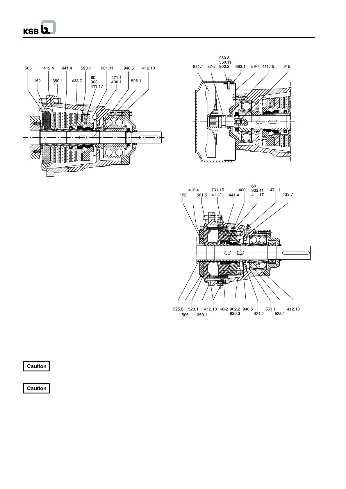
7.3.5.1 Removing an Air-Cooled Mechanical Seal
(Seal code 64)
Fig. 7.3-10
N.B.: This mechanical seal design is used for application
temperatures fom 140
0
C to 200
0
C and Multitec sizes 32 to 100.
The pump shall only be coupled to a motor with enclosure IP 55.
- Remove bearing acc. to sections 7.3.3.1 or 7.3.3.2.
- Remove O-ring 412.10.
- Pull of spacer sleeve 525.1.
- Loosen bolts 901.11.
- Remove bearing housing 350.1
- Remove mechanical seal cover 471.1 with the seat ring and
gasket 400.1.
- Remove key 940.5.
- Pull off sleeve 523.1 with the rotating assembly of mechanical
seal 433.7. (Two holes are supplied in the sleeve for engaging
a pull-off device).
- Take off sealing housing 441.1.
- Remove O-ring 412.4.
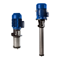
In case of a between-bearings pump (installation type/pump
version C or D) the mechanical seal shall be removed as follows
:
- Remove screws 900.2 and hood 683.1.
- Undo axle 87-5 together with fan impeller 831.1.
- The threaded insert 915 has to remain in teh shaft 210.
For previous versions (prior to 03/2002) and
assembly in the factory, the axle 87-5 and the fan
impeller 831.1 were assembled using Loctite 222.
For previous version and re-installation, the axle
87-5 and the fan impeller 831.1 must be secured
with Loctite 222.
- Remove support 59-7.
- Dismantle the bearing as described in section 7.3.3.1 as well
as spacer sleeve 525.1 and bearing housing 350.1
The removal of the mechanical seal is done as described above.
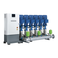
7.3.5.2 Dismantling of Water-Cooled Mechalical Seal
(Seal code 64)
N.B.: This application concerns the operation at temperatures
ranging from 140 to 200
0
C and sizes 125 and 150 (optional for
sizes 32 to 100).
- Drain pump and unscrew circulation line using the pipe unions
731.15.
- Remove rolling element bearing according to chapters 7.3.3.1
and 7.3.3.2.
- Remove O-ring 412.10.
- Pull off spacer sleeve 525.1.
- Unscrew nuts 920.3.
- Take off bearing housing 350.1.
- Remove mechanical seal cover 471.1 together with the seat
ring and gasket 400.1.
- Remove key 940.5.
- Pull off sleeve 523.1 with the rotating assembly of the
mechanical seal 433.7. (Two holes are provided in the sleeve
for engaging a pull-off device).
- Remove cooling jacket 66-2.
- Take off seal housing 441.4.
- Remove O-ring 412.4.
16