Multitec
7.3.5.3 Removing a Double-Acting Mechanical
Seal
Mechanical seals in tandem, face-to-face and back-to-back
arrangement are fitted as per customer specifications. There is
a wide variety of variants, types and brands. Please refer to the
general drawing and the documentation supplied with the pump
for orientation.
7.3.6 Dismantling the Hydraulic Elements
- Remove the bearings as described in sections 7.3.3.1 and
7.3.3.2 and the shaft seals as described in sections 7.3.4 and
7.3.5.
It possible, place the hydraulic system in vertical position and
start dismantling it from the discharge end.
- Loosen the four tie bolts 905.
- Remove discharge casing 107 and then the hydraulic system.
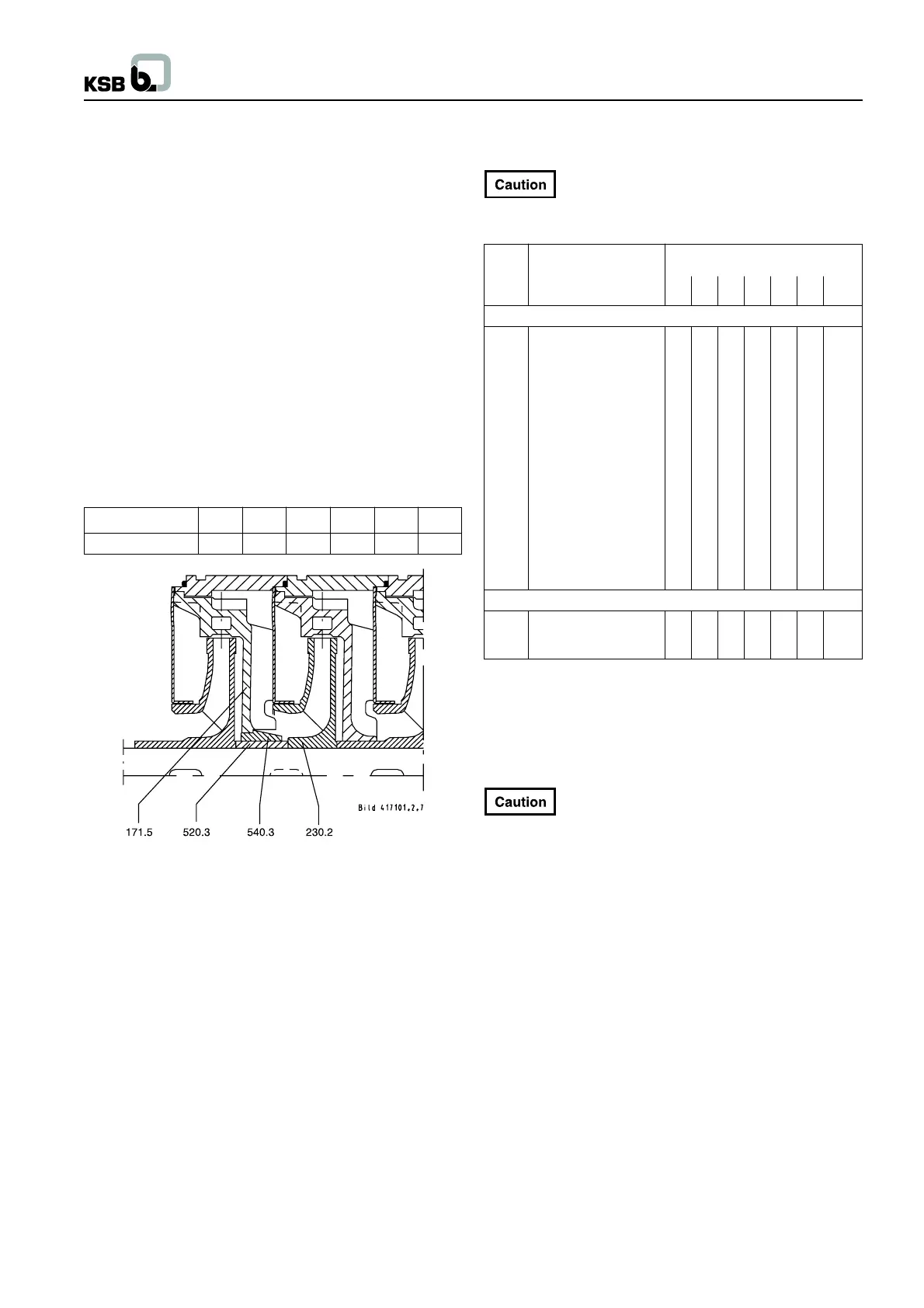
N.B.: The pump version A/B/C/D in material variants 22/23/30
have an intermediate bearing in the middle stage as of the number
of stages listed in the table (see Fig. 7.3-12).
Pump size 32 50 65 100 125 150
No. of Stages 8 7 6 6 5 6
Fig. 7.3-12
540.3 Intermediate bearing-bush
520.3 Intermediate bearing-sleeve
171.5 Intermediate bearing-diffuser
230.2 Intermediate bearing-impeller
7.3.7 Recommended Spare Parts Stock for 2
Years’ Continuous Operation
We recommend to replace different wear parts
(such as rolling element bearings, sealing elements,
circlips etc.) whenever the entire hydraulic system is dismantled
(See spare parts list below).
Part No. Description Number of pumpr
(including stand-by pumps)
2 3 4 5 6+7 8+9 10 and
more
For shaft seal codes 65 and 66 (gland packing)
210 Shaft with small parts 1 1 2 2 2 3 30 %
230 Impeller (set = S) 1 1 1 2 2 3 30 %
231 Suction impeller 1 1 1 2 2 3 30 %
320.1 Fixed bearing (set) 1 1 2 2 3 4 50 %
320.2 Radial bearing 1 1 2 2 3 4 50 %
381 Bearing cartridge 1 1 2 2 3 4 50 %
411 V-ring (set) 4 8 8 8 9 12 150 %
412 O-ring (set = S) 4 8 8 8 9 12 150 %
461 Gland packing (set) 4 6 8 8 9 12 150 %
502
1)
Casing wear ring (set) 2 2 2 3 3 4 50 %
520 Sleeve 1 1 2 2 3 4 50 %
524 Shaft protecting sleeve 2 2 2 3 3 4 50 %
525 Spacer sleeve 2 2 2 3 3 4 50 %
529 Bearing sleeve 1 1 2 2 3 4 50 %
540 Bush 1 1 1 2 2 3 30 %
550.1
2)
Disc 2 2 2 3 3 4 50 %
59-4 Balance drum 1 1 1 2 2 3 30 %
For shaft seal codes 61, 62, 63 and 64 (with mechanical seal)
433 Complete mechanical seal 2 3 4 5 6 7 90 %
3)
523 Shaft sleeve (set) 2 2 2 3 3 4 50 %
1) only pump sizes 125 and 150
2) only pump sizes 32 to 100
3) Parts 461 and 524 unassembled
N.B.: Please always indicate the works number stamped onto
the pump name plate when ordering spare parts.
7.4 Reassembly
The pump shall be reassembled in accordance with
the rules of sound engineering practice :
- Under no Circumstances use force.
- Due to their weight, some pump components must be
supported during reassembly.
- Before reassembly, the locating surfaces of the individual
components must be coated with a mounting aid in compliance
with hygienic health and safety regulations.
- The properties of new pump components must not be altered
without prior consultation with our technical departments.
- The parts must be clean and free from shavings or dust.
- Reassembly is effected in reverse order to dismantling.
- The tightening torques indicated must be complied with. Avoid
the use of mounting aids as far as possible. Should amounting
aid be required after all, use a commercially available contact
adhesive, e.g. Pattex, HYLOMAR or Epple 33, after prior
consultation with our technical departments. The adhesive
must only be applied at selected points and in thin layers. Do
not use cyano-acrylate adhesives (quick-setting adhesives).
17