Multitec
5.3.1 Aligning the Pump / Drive
Coupling guard
In compliance with the accident prevention
regulations the pump must not be operated without
a coupling guard / a guard on the drive lantern. If the customer
specifically requests not to include a coupling guard / lantern
guard in our delivery, then the operator must supply one.
Baseplate-mounted units
After fastening the baseplate on the foundation, the
coupling must be thoroughly checked and the pump
unit be realigned (at the motor), if required.
Prior to checking the alignment/realignment, loosen the pump
feet and retighten without transmitting any stresses or strains.
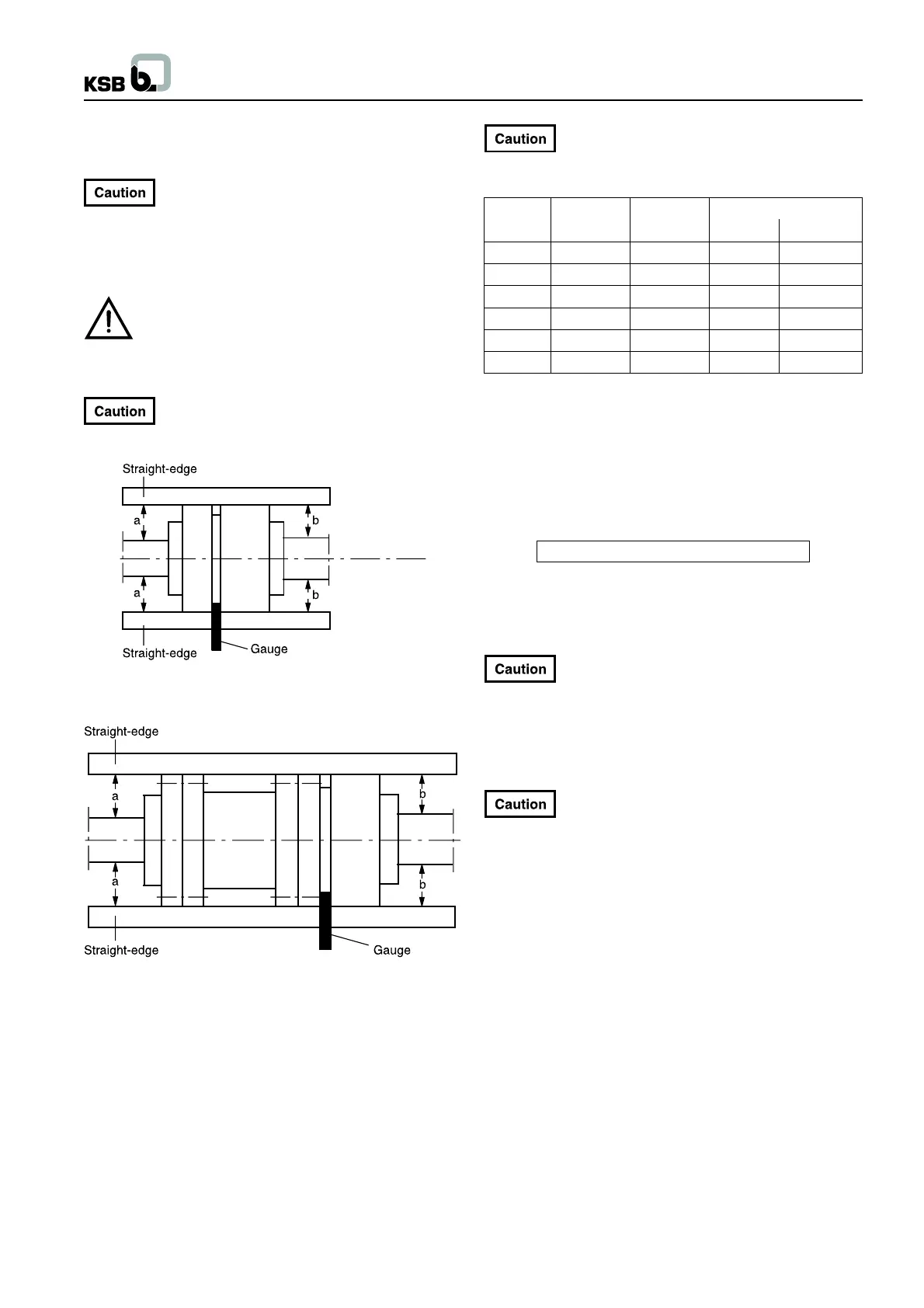
Coupling check and realignment must be effected
even if pump and motor are supplied completely
assembled and aligned on a common baseplate.
Fig. 5.3-3 Aligning the coupling with the help of a gauge
and straight-edge
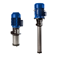
Fig. 5.3-4 Aligning a spacer-type coupling
The radial and axial deviation between the two coupling halves
shall not exceed 0.1 mm.
For product temperatures of 120
0
C and higher, the
foot bolts to secure the pump on the baseplate are
to be tightened with torques according to the following table :
MTC Thread Strength
Torque
drive non-drive
32 M 12 4.6 30 Nm 15 Nm
50 M 12 4.6 30 Nm 15 Nm
65 M 16 4.6 60 Nm 30 Nm
100 M 20 4.6 120 Nm 60 Nm
125 M 20 4.6 120 Nm 60 Nm
150 M 30 4.6 450 Nm 200 Nm
This will avoid that longitudinal increase of the pump by thermal
expansion will lead to warping and deformation.
As the thermal expansion in height of pump and motor may differ,
this has to be considered when aligning the coupling of pump
units handling temperatures of 100
0
C and higher. To estimate
the increase in height, the following equation can serve as a guide
to calculate by how much the motor has to be elevated in
relationship to the pump :
H [mm] = 1/100000 * (Tp * Hp - Tm * Hm)
Tp = Temperature difference pump - environment (
0
C)
Hp = Height of pump axis [mm]
Tm = Temperature difference motor - environment (
0
C)
Hm = Height of motor axis [mm]
In any case, also when using this correction, the
coupling has to be re-aligned when the unit is in
warm condition from operation.
Close-coupled pumps and vertical pumps
Alignment between the motor and the pump is ensured by the
centering effect between the motor flange and the drive lantern
flange. It must be easy to rotate the shaft.
For the Multitec V32-65, the dimensions for the
setting of the coupling alignment have to be
considered during assembly (see page no. 31).
Final check
Re-check the alignment as described in the sections above. It
must be easy to rotate the shaft by hand at the coupling. Check
the integrity and proper functioning of all connections.
5.4 Connecting the Piping
Suction lift lines shall be laid with a rising slope towards the pump
and suction head lines with a downward slope towards the pump,
to avoid the formation of air pockets.
With short pipelines, the nominal diameters shall be at least equal
to the nominal diameters of the pump nozzles. For long pipelines
the most economical nominal diameter has to be determined from
case to case.
Adapters to larger diameters should have a diffuser angle of
approx. 8 in order to avoid any pressure losses caused by of air
pockets or gas.
It is recommended to install check and shut-off elements in the
system, depending on the type of plant and pump.
5